

PN16

BURKERT 20114129 (Type 0331) is a direct-acting 3/2-way pivoted armature solenoid valve featuring universal circuit function T, brass flange body, NBR seals, DN 2.0 orifice, manual override, and 230 V AC operation.
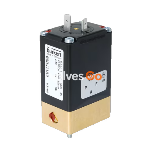
BURKERT 20114129 (Type 0331) is a direct-acting, media-separated 3/2-way pivoted armature solenoid valve engineered for aggressive or neutral gases and liquids. The valve utilizes an isolating diaphragm system that hermetically separates the medium chamber from the actuator coil, preventing corrosion, contamination, and thermal transfer to the processed fluid. Built with circuit function T for universal flow configuration, unit 20114129 delivers an orifice diameter of 2.0 mm (5/64"), a pressure operating range of 0 to 12 bar, and an operating flow rate Kv of 0.08 m³/h (QNn 85 l/min for gases).
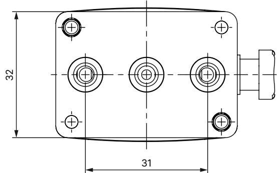
The unit is configured as a complete valve with a brass body and seat, NBR elastomeric seals rated 70 Shore A, a lockable mechanical manual override, and a standard Bürkert sub-base flange interface measuring 32 x 46 mm (Version A2). The electrical actuator is powered by 230 V AC at 50/60 Hz via a DIN EN 175301-803 Form A plug interface, achieving IP65 ingress protection when mounted with an approved cable plug.
Type 0331 pivoted armature valves operate without sliding internal cores in fluid contact. The armature pivots on an external fulcrum, and a flexible diaphragm isolates the fluid passage from the upper coil housing. This design eliminates friction-induced particle shedding and prevents media ingress into the magnetic core area.
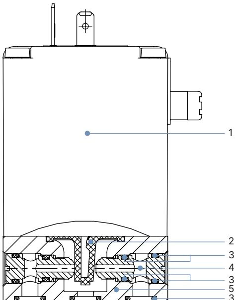
| Item | Component | Standard Specification / 20114129 Material |
|---|---|---|
| 1 | Solenoid Coil | Chemically resistant epoxy resin moulding (Class H) |
| 2 | Diaphragm | NBR (70 Shore A) [Standard variants also support EPDM, FKM, FFKM] |
| 3 | O-ring | NBR [Standard variants also support EPDM, FKM, FFKM] |
| 4 | Valve Seat | Brass [Variants support 1.4401 stainless steel, PP, PEEK] |
| 5 | Valve Body | Brass [Variants support 1.4401 stainless steel, PP, PEEK] |
NBR sealing components are compatible with neutral fluids such as compressed air, town gas, water, hydraulic oils, additive-free oils and greases, and technical oxygen within a temperature range of 0 °C to +80 °C.
Article 20114129 features Circuit Function T (CF T), configured as a direct-acting 3/2-way universal valve that rests closed in the de-energized state. Flow direction through the valve body is unrestricted:
The compression springs installed inside Type 0331 bodies are factory-selected for the nominal circuit function. When unit 20114129 is plumbed into alternative flow configurations, maximum working pressure limits change according to internal mechanical bias:
| Original Function | DN | Max Operating Pressure [bar] in Function A | Max Operating Pressure [bar] in Function B | Max Operating Pressure [bar] in Function C | Max Operating Pressure [bar] in Function D | Max Operating Pressure [bar] in Function E | Max Operating Pressure [bar] in Function F |
|---|---|---|---|---|---|---|---|
| Function T | 2.0 | 8.0 | 8.0 | 10.0 | 10.0 | 10.0 | 8.0 |
| Function T | 3.0 | 6.0 | 6.0 | 6.0 | 6.0 | 6.0 | 6.0 |
| Function T | 4.0 | 3.0 | 3.0 | 3.0 | 3.0 | 3.0 | 3.0 |
INFO
When operating a 3/2-way valve in 2/2-way configurations (Function A or Function B), fluid lines must be piped according to the 3/2-way port numbering scheme, leaving the unused port plugged or vented.
| Technical Parameter | Specification / Measured Value |
|---|---|
| Orifice Size | DN 2.0 mm (5/64") |
| Kv Flow Factor (Water) | 0.08 m³/h (DC frequency: 0.08 m³/h; AC 50/60 Hz: 0.10 m³/h) |
| QNn Flow Value (Air) | 85 l/min |
| Operating Pressure Range | 0.0 to 12.0 bar (Vacuum capability: -0.98 to 8.0 bar) |
| Nominal Voltage | 230 V AC, 50/60 Hz (Voltage tolerance: ±10%) |
| AC Coil Inrush Power | 30 VA |
| AC Coil Holding Power | 15 VA / 8 W (active power at operating temperature) |
| Switching Time Opening (AC) | 8 to 15 ms (measured at +20 °C, 6 bar at outlet, 0–90% pressure build-up) |
| Switching Time Closing (AC) | 8 to 15 ms (measured at +20 °C, 6 bar at outlet, 100–10% pressure reduction) |
| Max Switching Frequency | Dependent on thermal dissipation; continuous duty 100% ED on brass bodies |
| Fluid Viscosity Limit | Maximum 37 mm²/s |
| Ambient Temperature | Maximum +55 °C |
| Storage Temperature | -40 °C to +80 °C |
TIP
During extended downtime, executing at least 1 to 2 switching operations prior to process restart maintains diaphragm responsiveness and seats.
Type 0331 flange variants mount directly to baseplates, blocks, or Bürkert manifolds. Unit 20114129 has an overall installation length of 46 mm and body width of 32 mm.
WARNING
Do not use the solenoid coil as a lever arm when aligning or securing the valve assembly. Apply tightening torque only to the metal valve body.
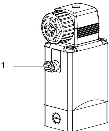
Unit 20114129 includes a mechanical manual override on the actuator body for system commissioning, dry running, and maintenance testing.
WARNING
When the manual override is locked in the manual position, the valve cannot be actuated electrically. Ensure the override is fully unlocked before restoring automatic control.
Electrical connection is established through three flat plug prongs arranged in Form A according to DIN EN 175301-803 (formerly DIN 43 650). Use a compatible cable socket such as Bürkert Type 2518 or Type 2509.
Type 0331 valves operate without dynamic shaft packings and require no periodic lubrication. Repairs involving internal pressure boundary components must be conducted by Bürkert factory service.
| Fault Condition | Possible Cause | Corrective Action |
|---|---|---|
| Valve does not switch | Supply voltage missing or out of ±10% tolerance | Verify line voltage matches 230 V AC type label rating |
| Electrical coil interrupted or short-circuited | Check coil continuity and resistance | |
| Operating pressure exceeds allowable limit (> 12 bar) | Verify line pressure does not exceed 12 bar | |
| Manual override locked in mechanical position | Disengage manual override by rotating counter-clockwise | |
| Valve does not close | Valve interior contaminated with solid particulates | Clean valve chamber; install upstream filter ≤ 500 µm |
| Manual override locked in engaged position | Rotate manual override counter-clockwise to unlock | |
| Coil overheats / hums | Core seized due to foreign matter or mechanical shock | Isolate power immediately; inspect core movement |
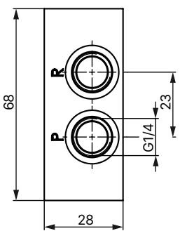
Type 0331 flange valves interface with single and multi-station aluminium, brass, or stainless steel manifold blocks with G 1/4 process connections.
| Accessory Description | Material / Electrical Spec | Article Number |
|---|---|---|
| Cable Plug Type 2518 (DIN EN 175301-803 Form A) | Without circuitry, 0–250 V AC/DC | 314802 |
| Cable Plug Type 2518 | With LED indicator, 12–24 V AC/DC | 314812 |
| Cable Plug Type 2518 | With LED and varistor, 12–24 V AC/DC | 314820 |
| Cable Plug Type 2518 | With rectifier, LED and varistor, 12–24 V AC/DC | 314816 |
| Cable Plug Type 2509 (DIN EN 175301-803 Form A) | Standard unshielded, 0–250 V AC/DC | 137943 |
| Locking Circlip | Prevents inadvertent manual override activation | 013372 |
| Manifold Block G 1/4 (2 Valve Slots, L = 69 mm) | Anodized aluminium / Brass (612071) | 005045 |
| Manifold Block G 1/4 (4 Valve Slots, L = 143 mm) | Anodized aluminium / Stainless steel (658925) | 005294 |
| Manifold Block G 1/4 (6 Valve Slots, L = 217 mm) | Anodized aluminium / Brass (006326) | 005296 |
| Manifold Block G 1/4 (8 Valve Slots, L = 291 mm) | Anodized aluminium | 006074 |
| Blanking Cover Plate (Unoccupied Slot) | Stainless steel / FKM seal | 265294 |
| Blanking Cover Plate (Unoccupied Slot) | Anodized aluminium / NBR seal | 005625 |
Explore similar products in our catalog


