

PN16

BURKERT 20114550 is a 24-slot Type 8652 AirLINE valve island with aluminium AirLINE Quick base, Industrial Ethernet (PROFINET, EtherNet/IP, Modbus TCP, EtherCAT), 48 CF-C valve functions, and integrated HotSwap.
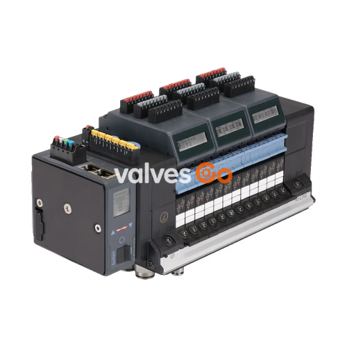
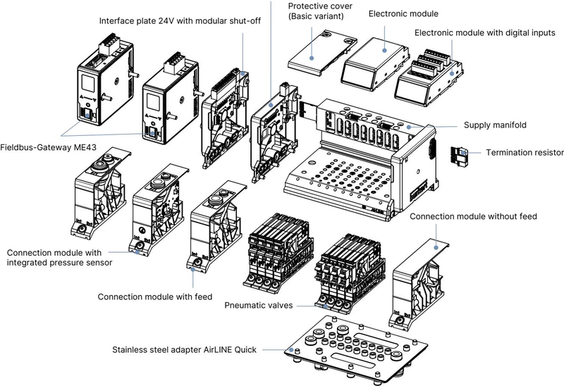
BURKERT 20114550 (Type 8652 AirLINE) is a 24-slot pneumatic valve island configured with an anodised aluminium AirLINE Quick adapter plate, an intermediate pneumatic supply module, and 24 dual 3/2-way normally closed (CF-C) Type 6534 pilot valves. The assembly provides 48 discrete pneumatic control channels in a compact 11 mm station pitch, designed specifically for process automation environments where space optimisation and process reliability are mandatory.
Communication is handled by a high-performance Industrial Ethernet fieldbus module featuring dual RJ45 ports (X1 and X2). The module natively supports PROFINET IO, EtherNet/IP, Modbus TCP, EtherCAT, and CC-Link IE Field Basic. Process security is enhanced through integrated check valves in the common exhaust air ducts (ports 3 and 5), preventing unwanted actuator movement caused by backpressure spikes, while pneumatic HotSwap functionality in the P-channel (port 1) allows replacement of pilot valves during active operation without system depressurisation.
| Technical Parameter | Specification / Rating |
|---|---|
| Product Type | Type 8652 AirLINE Valve Island |
| Article Number (Ident No.) | 20114550 |
| Number of Valve Slots | 24 slots (11 mm station width) |
| Populated Valve Type | Type 6534 dual 3/2-way CF-C (normally closed) |
| Total Controlled Functions | 48 pneumatic outputs |
| Operating Pressure Range | -1.00 bar to 10.00 bar (vacuum to 10 bar) |
| Auxiliary Pilot Air Pressure | 3.00 bar to 10.00 bar (internal supply) |
| Nominal Air Flow Rate ($Q_{\text{Nn}}$) | 310 l/min (air at +20 °C, 6 bar inlet, 1 bar $\Delta p$); 270 l/min for CF-C |
| HotSwap Air Flow Impact | Flow rate reduced by approximately 3% |
| Operating Voltage | 24 V DC (±10%), residual ripple 1 Vss |
| Valve Coil Power | 0.7 W (0.175 W after electronic power reduction) |
| Valve Coil Current | 29 mA (10 mA after electronic power reduction) |
| Duty Cycle | 100% ED (continuous operation) |
| Switching Time | Opening: 15 ms, Closing: 15 ms (ISO 12238) |
| Operating Medium | Lubricated or dry compressed air, neutral gases (ISO 8573-1:2010 Class 7.4.4, 5 µm filter) |
| Body / Seal Material | Polyamide (PA) / NBR and PUR seals |
| AirLINE Quick Plate Material | Anodised aluminium (adapter plate) |
| Pneumatic Port Sizes | Supply (1): D10 mm brass; Working ports (2, 4): D6 mm brass |
| Additional Supplies | Left, right, and center intermediate feed: D6 and D10 push-in fittings |
| Degree of Protection | IP20 standalone; IP65 inside closed cabinet with AirLINE Quick plate |
| Ambient / Medium Temperature | -10 °C to +55 °C |
| Storage Temperature | -20 °C to +60 °C |
| Total Current & Overvoltage | Electrical safety Class III (DIN EN 61140, VDE 0140) |
The AirLINE Quick adapter plate drastically reduces the footprint and assembly time inside the control cabinet. Instead of routing 48 flexible tubing lines through separate cabinet cable glands or bulkheads, the valve island mounts directly into a cutout in the cabinet floor or side wall.
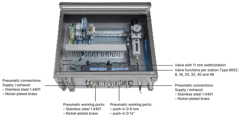
All working lines (D6 push-in connections) and main supply lines (D10 push-in connections) emerge directly outside the enclosure. The anodised aluminium adapter plate provides a robust mechanical seal, preserving an ingress protection rating of IP65 for the electrical and pneumatic components enclosed within the cabinet.
Installation Clearance for HotSwap
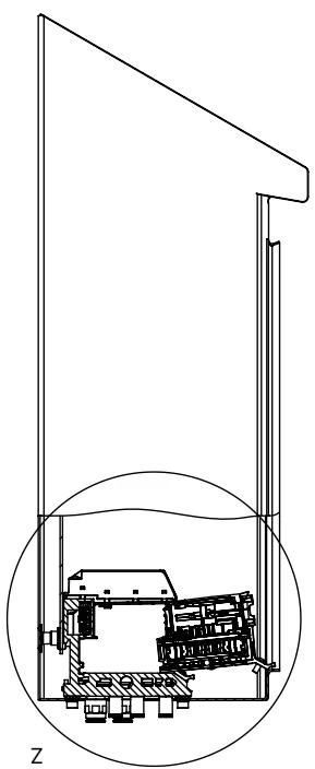
When installing the valve island inside the control cabinet, adhere to the minimum spacing from the cabinet front edge and walls to enable smooth valve removal and insertion under pressure.
The Type 8652 with 24 valve slots and an integrated intermediate feed module features extended length dimensions compared to basic 4-, 8-, and 12-slot variants.
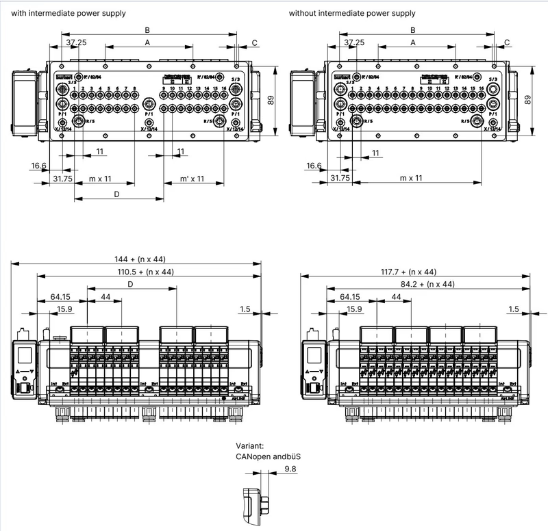
| Configuration Variant | A (mm) | B (mm) | C (Fastening) | D (mm) | m | m' | n |
|---|---|---|---|---|---|---|---|
| 16-fold with intermediate supply | 112 | 224 | 10× M5 | 114.3 | 7 | 7 | 4 |
| 20-fold with intermediate supply | 134 | 268 | 10× M5 | 158.3 | 11 | 7 | 5 |
| 24-fold with intermediate supply (20114550) | 156 | 312 | 10× M5 | 158.3 | 11 | 11 | 6 |
| 16-fold without intermediate supply | 99 | 198 | 10× M5 | — | 15 | — | 4 |
| 20-fold without intermediate supply | 121 | 242 | 10× M5 | — | 19 | — | 5 |
| 24-fold without intermediate supply | 143 | 286 | 10× M5 | — | 23 | — | 6 |
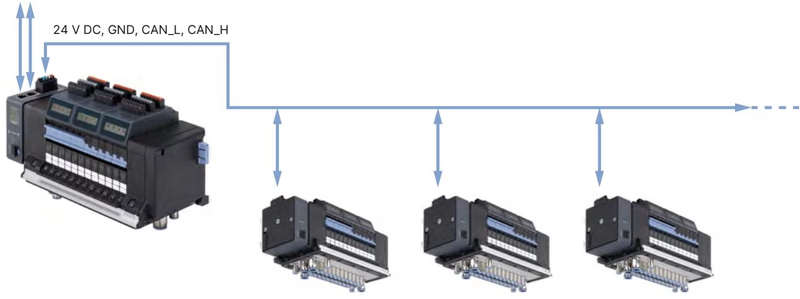
The valve island utilizes separate electrical supplies for communication electronics and pneumatic valve coils, isolating digital processing from inductive switching disturbances.
| Terminal | Wire Colour | Signal Assignment | Conductor Cross-Section |
|---|---|---|---|
| 1 | Red | +24 V DC (Communication) | $\le 1.5\text{ mm}^2$ |
| 2 | White | CAN_H (büS connection) | $\le 1.5\text{ mm}^2$ |
| 3 | Green | SHIELDING | $\le 1.5\text{ mm}^2$ |
| 4 | Blue | CAN_L (büS connection) | $\le 1.5\text{ mm}^2$ |
| 5 | Black | 0 V DC (GND) | $\le 1.5\text{ mm}^2$ |
| Pin | Wire Colour | Signal Assignment | Conductor Cross-Section |
|---|---|---|---|
| 1 | Red | AUX +24 V DC (Pneumatic Valves) | $\le 1.5\text{ mm}^2$ |
| 2 | Black | 0 V DC (GND) | $\le 1.5\text{ mm}^2$ |
| Pin | Signal | Pin | Signal |
|---|---|---|---|
| 1 | TX+ (Transmit Data +) | 5 | N.C. (Not connected) |
| 2 | TX- (Transmit Data -) | 6 | RX- (Receive Data -) |
| 3 | RX+ (Receive Data +) | 7 | N.C. (Not connected) |
| 4 | N.C. (Not connected) | 8 | N.C. (Not connected) |
Article 20114550 comes factory-fitted with 24 units of Type 6534 in Circuit Function C ($2\times 3/2$-way normally closed). When maintenance or line retooling is required, genuine Burkert Type 6534 pilot valves and blanking plates can be ordered using the following reference identifiers.
| Circuit Function | Nominal Diameter | $Q_{\text{Nn}}$ Air | Pressure Range | Response Time Open / Close | Coil Voltage | Valve Article No. (incl. screws) | Spare Part Set REF |
|---|---|---|---|---|---|---|---|
| C: $2\times 3/2$-way NC (Installed on 20114550) | 4 mm | 270 l/min | Vac...10 bar | 15 ms / 15 ms | 24 V DC | 301374 | 296031 |
| C: single 3/2-way NC | 4 mm | 270 l/min | Vac...10 bar | 15 ms / 15 ms | 24 V DC | 20102334 | 20088974 |
| D: $2\times 3/2$-way NO | 4 mm | 310 l/min | Vac...10 bar | 15 ms / 15 ms | 24 V DC | 301375 | 296032 |
| H: 5/2-way monostable | 4 mm | 290 l/min | Vac...10 bar | 20 ms / 25 ms | 24 V DC | 301376 | 296033 |
| Z: 5/2-way bistable (impulse) | 4 mm | 290 l/min | Vac...10 bar | 20 ms / 25 ms | 24 V DC | 301377 | 296034 |
| L: 5/3-way closed center | 4 mm | 275 l/min | Vac...10 bar | 15 ms / 15 ms | 24 V DC | 301380 | 296036 |
| M: 5/3-way pressurized center | 4 mm | 300 l/min | Vac...10 bar | 20 ms / 20 ms | 24 V DC | 301379 | 296035 |
| N: 5/3-way exhausted center | 4 mm | 300 l/min | Vac...10 bar | 20 ms / 20 ms | 24 V DC | 301381 | 296039 |
| Dummy blanking plate | — | — | — | — | — | 335779 | 327614 |
Auxiliary Pilot Air Requirements
For vacuum or working pressures below 3 bar, separate auxiliary pilot pressure of 3 bar to 10 bar must be applied. In model 20114550, auxiliary pilot air is routed internally from the main feed.
Type 8652 valve islands with explosion-protection classification comply with European ATEX Directive 2014/34/EU, IECEx, CCC, and North American NEC standards for Zone 2 and Zone 22 applications.
Special Conditions for Safe Use in Hazardous Locations
Explore similar products in our catalog


