Up to 99.8% Efficiency

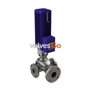
BURKERT 20114635 Type 3361 electromotive 2-way globe control valve. Features stainless steel body, G 1/2" thread, 24 V DC supply, AG2 actuator, and integrated process controller.
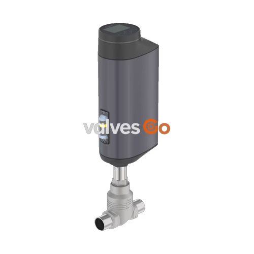
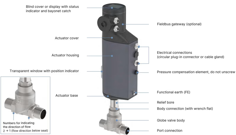
BURKERT 20114635 Type 3361 electromotive 2-way globe control valve is the solution when it comes to control tasks under demanding operating conditions. The electromotive actuator with ball screw positions the control cone with highest precision. A unique feature is its high positioning speed up to 6 mm/s that reacts almost delay-free to process signals and that can be varied according to customer demands. Pressure variations or shocks in the medium are not transferred to the valve position. The flow-optimised valve body can be equipped with different valve seats for a precise adaptation according to customer needs. Actuator and valve are adapted perfectly to each other with a closed design and robust surface, ensuring the hygienic requirements of fast and residue-free cleaning. Harsh environmental conditions are no problem for the Type 3361 because of the degree of protection IP65/IP67 and its high impact and vibration resistance.
| Product properties | |
|---|---|
| Design | Globe control valve |
| Nominal diameter | DN 15, NPS 1/2" |
| Safety setting in case of power failure | With energy storage SAFEPOS energy-pack: open, closed or freely programmable position. Without energy storage: blocked in last position |
| Flow direction | Against closing direction (below seat) |
| Controller variant | Process controller |
| Weight | AG2: up to 5.5 kg (Total weight including valve body depending on port connection) |
| Performance data | |
|---|---|
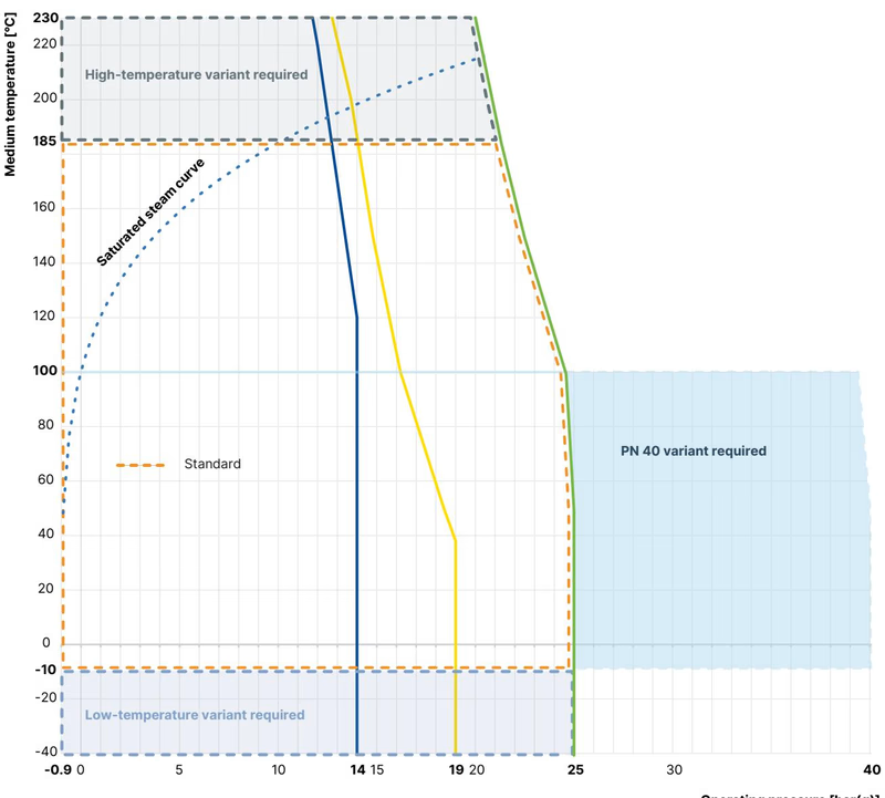
| Operating pressure | 0...25 bar(g) |
| Nominal pressure | PN 25 (DIN EN 1333), Class 150 (DIN EN 1759) |
| Kv value | 1.25 m³/h |
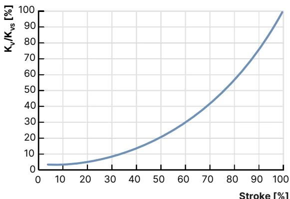
| Flow characteristic | Equal percentage 50:1 |
| Closing time | AG2: 3.3...6.6 s (Depending on travel speed, stroke and operating conditions) |
| Travel speed | 6 mm/s (for AG2 actuator force 1300 N) |
| Dead band of the position control | ± 0.1 % |
| Electrical data | |
|---|---|
| Operating voltage | 24 V DC ± 10 % (maximum residual ripple 10 %) |
| Operating current | AG2: maximum 3 A (at maximum load and including 1 A charging current of the optional energy storage SAFEPOS energy-pack). At minimum operating temperature additionally 2 A |
| Protection class | III (DIN EN 61140) |
| Duty cycle | 100 % |
| Standby consumption | 2...5 W |
| Medium data | |
|---|---|
| Operating medium | Steam, neutral gases, water, alcohols, oils, fuels, hydraulic fluids, salt solutions, organic solvents |
| Medium temperature | -10 °C...+ 185 °C |
| Viscosity | Up to 600 mm²/s |
| Environment and installation | |
|---|---|
| Ambient temperature | - 25 °C...+ 65 °C (only without additional modules) |
| Degree of protection | IP65/IP67 (DIN EN 60529), NEMA 4X |
| Installation position | Any, preferably with actuator upright |
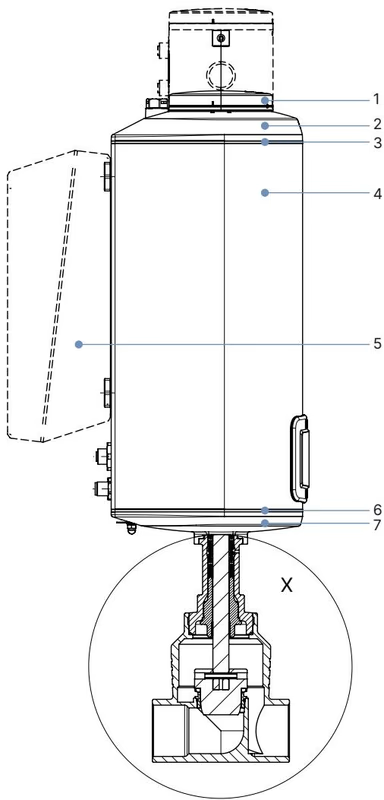
| No. | Component | Material |
|---|---|---|
| 1 | Display housing/blind cover/gateway housing | PPS (standard), stainless steel 1.4301 (for ATEX/IECEx) |
| 2 | Actuator cover | PPS |
| 3 | Seal | EPDM |
| 4 | Actuator housing | Powder-coated aluminium |
| 6 | Seal | EPDM |
| 7 | Actuator base | PPS |
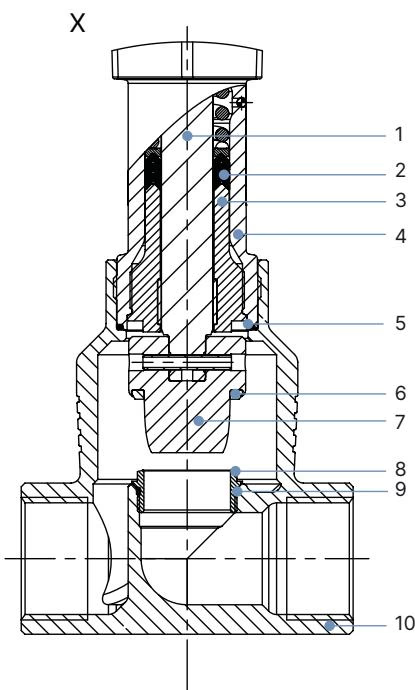
| No. | Component | Material |
|---|---|---|
| 1 | Spindle | Stainless steel 1.4401 (316)/1.4404 (316L) |
| 2 | Spindle seal | PTFE V-seals (filled) with spring compensation |
| 3 | Spindle guide | Stainless steel 1.4404 (316L) |
| 4 | Packing gland tube | Stainless steel 1.4401 (316) |
| 5 | Seal valve body | Graphite or PTFE |
| 6 | Seat seal | Stainless steel 1.4571 (optionally hardened), PTFE or PEEK seal washer |
| 7 | Control cone | Stainless steel 1.4571 (optionally hardened) |
| 8 | Valve seat | Stainless steel 1.4571 (optionally hardened) |
| 9 | O-ring valve seat | EPDM or PTFE |
| 10 | Valve body | Stainless steel CF3M |
INFO
Dimensions in mm, unless otherwise stated. Dimensions without sealing function: the actuator is raised by approx. 2 mm in the closed position.
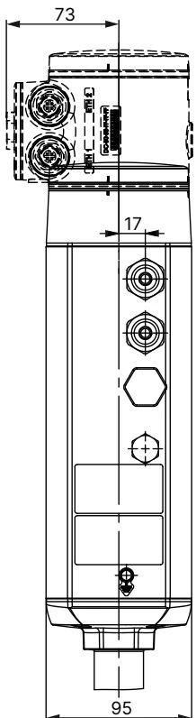
| Nominal diameter | NPS | H1 Standard variant | H2 Fieldbus variant |
|---|---|---|---|
| DN 15 | 1/2 | 417 | 489 |
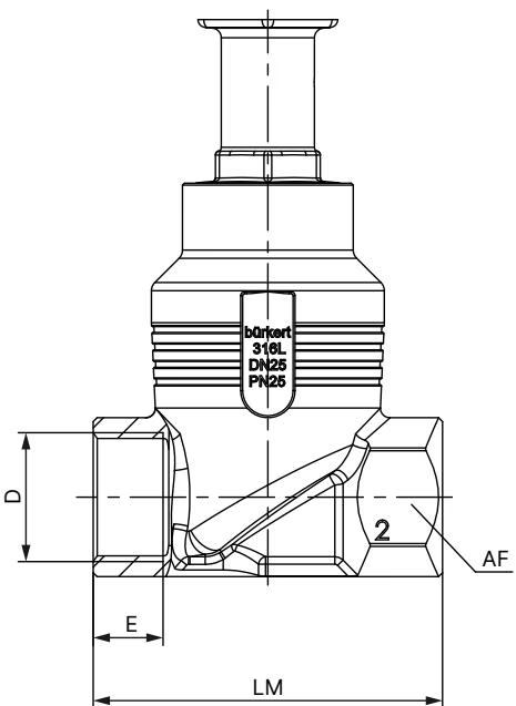
| Nominal diameter | NPS | G | NPT | RC | LM | AF |
|---|---|---|---|---|---|---|
| DN 15 | 1/2 | 14 | 13.7 | 13.2 | 65 | 27 |
Equal-percentage flow characteristic according to DIN EN 60534-2-4.
In addition to the maximum operating pressures, the application range of Bürkert process valves is limited by the nominal pressure in accordance with the relevant standard.
The additionally implemented PID controller allows process control. The set-point position of the valve is calculated from the external signal (e.g. level, pressure, flow rate, temperature) for the process set-point and the actual process value via the control parameters (PID controller).
WARNING
Risk of injury from high pressure. Before working on the system or device, switch off the pressure and vent or drain lines. Spare parts may be replaced only by trained technicians and with the appropriate tools.
Explore similar products in our catalog