

PN16

BURKERT 20122777 (Type 8640 REV3) is an 11 mm modular pneumatic valve island featuring 4x (2x 3/2-way) NC valves, AirLINE Quick aluminium adapter, G 1/4 supply, D6 bottom ports, and single wiring.
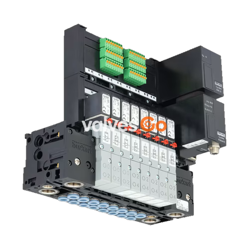
BURKERT 20122777 (Type 8640 REV3) is a modular pneumatic valve island configured with four Type 6524 double valve stations providing eight independent 3/2-way normally closed (Circuit Function C C) channels. Built with an 11 mm station width and an anodized aluminium AirLINE Quick adapter plate, the unit mounts directly to the control cabinet floor or wall, routing G 1/4 supply connections and D6 push-in working lines straight out of the bottom of the enclosure. The system utilizes individual stranded wiring without internal fieldbus communication, operating across an operating pressure range of 2.5 to 10.0 bar and temperatures from 0 °C to +50 °C with IP20 ingress protection.

| Parameter | Specification |
|---|---|
| Product Type | Modular pneumatic valve block Type 8640 |
| Article Number (SKU) | 20122777 |
| Hardware Generation | Revision 3 (REV3) |
| Valve Configuration | 4x (2x 3/2-way) Circuit Function C C (Normally Closed) |
| Total Controlled Functions | 8 solenoid pilot channels |
| Station Width | 11 mm per station |
| Operating Pressure Range | 2.5 to 10.0 bar (overpressure to atmosphere) |
| Flow Rate QNn (Air) | 300 l/min (at +20 °C, 6 bar inlet pressure, 1 bar delta P) |
| Medium Temperature Range | 0 °C to +50 °C |
| Ambient Temperature Range | 0 °C to +55 °C |
| Operating Medium | Oil-free or lubricated dry compressed air, neutral gases (5 µm filtration recommended) |
| Compressed Air Quality | ISO 8573-1:2010, Class 7.4.4 |
| Air Supply Ports 1(P), 3(R), 5(S) | G 1/4 (nickel-plated brass connections) |
| Working Ports 2, 4 | D6 mm push-in coupling (nickel-plated brass, bottom exit) |
| Adapter Plate Material | Anodized aluminium (AirLINE Quick) |
| Base Module Material | Polyamide (PA) |
| Sealing Materials | FKM, NBR, and PUR |
| Operating Voltage | 24 V DC (±10%, residual ripple max. 1 Vss) |
| Power Consumption per Slice | 2 x 0.8 W (with integrated electronic power reduction) |
| Electrical Protection Class | III according to VDE 0580 |
| Ingress Protection Class | IP20 (IP65 inside closed control cabinet) |
| Operating Mode | Continuous operation (100% duty cycle) |
| Manual Override | Standard lockable turn/push mechanism on each valve |
BURKERT 20122777 is fitted with four Type 6524 double valve units. Each unit integrates two independent pilot flipper valves (Type 6144) acting upon pneumatic seat valve mechanics. The flipper mechanism permits switching of pneumatic pressures up to 10 bar with minimal coil power consumption and fast dynamics.
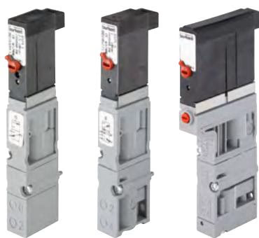
| Characteristic | Type 6524 Double Valve (2x 3/2-way CF C) |
|---|---|
| Circuit Function | 2x 3/2-way servo-controlled, normally closed (Circuit Function C C) |
| Nominal Diameter (DN) | 4.0 mm |
| Flow Rate QNn (Air) | 300 l/min |
| Pressure Range | 2.5 to 10.0 bar |
| Switching Time: Opening | 12 ms (measured per ISO 12238) |
| Switching Time: Closing | 20 ms (measured per ISO 12238) |
| Rated Coil Power | 2 x 0.8 W with integrated power reduction |
| Flange Interface Standard | FM20 (standardized REV3 pneumatic interface) |
| Fastening Screws | 2 screws M2 x 28 per valve body |
Each valve slice incorporates mechanical manual overrides as standard, allowing manual activation during commissioning or maintenance.
Manual Override Operation
To activate a valve manually, press the manual override pin and turn it 90° clockwise until it stops. The override locks in position. Only operate the manual override when electrical power is switched off. Unlock before returning to electrical automation.
The AirLINE Quick system integrates the pneumatic valve block directly into a cut-out on the control cabinet floor or wall. By sealing directly against the enclosure wall, AirLINE Quick eliminates individual bulkheads, internal push-in fittings, and piping runs between the valve island and external field equipment.
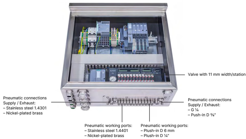
• Enclosure Integration: Adapts directly to the control cabinet boundary, significantly reducing cabinet volume requirements.
• Direct Connection: Supply air ports 1(P), 3(R), and 5(S) with G 1/4 threads and eight D6 mm working lines route directly out of the bottom of the pneumatic module through the aluminium adapter plate.
• Metallic Strength: Adapter plate machined from anodized aluminium with nickel-plated brass port fittings, providing mechanical rigidity at the cabinet interface.
The Type 8640 pneumatic sub-assembly consists of interconnected polyamide blocks joined via built-in snap connectors and secured with O-ring sealing faces.
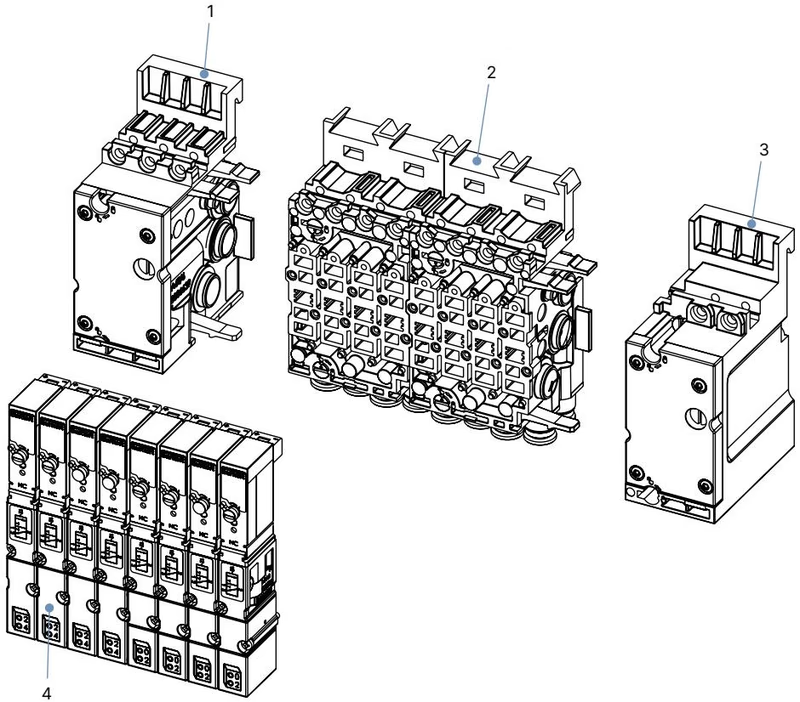
Pneumatic Connection Module Left: Left termination unit providing primary supply air port 1(P) and exhaust ports 3(R) / 5(S).
Basic Pneumatic Module (4-fold, 11 mm): Intermediate polyamide manifold housing four station slots with bottom-exiting D6 push-in working ports.
Pneumatic Connection Module Right: Right termination unit for manifold channel completion or supplementary supply staging.
Valves: Four Type 6524 2x 3/2-way double valve slices fastened onto the basic module via M2 x 28 fixing screws.
BURKERT 20122777 is manufactured under hardware revision REV3. Revision 3 incorporates distinct mechanical and fluidic improvements over earlier REV1 and REV2 revisions:
• Working Connection Layout: Working ports on REV3 pneumatic base modules feature a wavy channel arrangement rather than the parallel layout of REV1/REV2.
• Hose Release Rings: REV3 push-in fittings use blue release rings (REV1/REV2 used black rings).
• Flange Standard: REV3 single valves utilize the standardized FM20 flange interface. Replacement double valves Type 6524 must match the FM20 specification.
• Internal Flow Optimization: Reduced flow resistance through the pneumatic base channel; flow reduction when using integrated P-shut-off modules is limited to 20% (compared to up to 50% in REV1/REV2).
Article 20122777 is configured for individual wiring (single wiring connection) without an internal communication fieldbus node. Control signals are routed directly to the individual coil interfaces through screw-type terminals:
• Operating Voltage: 24 V DC (tolerance ±10%, maximum residual ripple 1 Vss).
• Common Return: Looped-through ground potential across the collective terminal module.
• Maximum Total Current: Up to 3 A across the valve assembly.
• Electrical Isolation: Protection Class III according to VDE 0580.
• Degree of Protection: IP20 across terminal modules; when installed within a sealed control cabinet complying with IP65, the entire pneumatics assembly maintains cabinet-level environmental protection.
Installation requires clean, de-energized, and depressurized operating environments. Pneumatic connection requires calibration of hose lines and adherence to push-in retention standards.
Depressurization and Safety
High pneumatic pressure presents severe injury hazards from escaping media or loose tubing. Fully vent and depressurize all supply and working lines before mounting, uncoupling, or maintaining the valve island. Disconnect the 24 V DC power supply and secure against accidental re-energization.
Pneumatic hose lines connected to the D6 push-in fittings must meet the following criteria:
• Minimum hardness of 40 Shore D in accordance with DIN 53505 or ISO 868.
• Outer diameter tolerances complying with DIN 73378 (PA: ±0.08 mm; PU: ±0.10 mm).
• Burr-free, undamaged surface cut squarely at 90°.
| Hose Outer Diameter (OD) | Minimum Tensile Force: PA Hose [N] | Minimum Tensile Force: PU Hose [N] |
|---|---|---|
| 3 mm (1/8") | 60 | 25 |
| 4 mm (5/32") | 70 | 50 |
| 6 mm (1/4") | 120 | 100 |
| 8 mm (5/16") | 170 | 150 |
| 10 mm (3/8") | 250 | 200 |
| 12 mm (1/2") | 300 | 200 |
| 14 mm | 300 | 250 |
| 16 mm (5/8") | 350 | 300 |
Tubing Verification
Cut hoses strictly perpendicular to the tube axis. Oblique cuts impair claw retention and lead to peripheral leakage or line detachment under pressure. For soft polyurethane (PU) tubing subject to mechanical movement, use support sleeves (ID 20099400) inside the hose end.
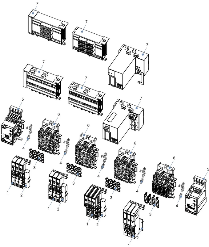
Maintenance and component replacements on the 11 mm REV3 platform require exact part-number matching:
| Item / Description | Content / Details | Article No. |
|---|---|---|
| Replacement Valve Type 6524 (2x 3/2-way CF C, 2.5–10 bar, 24 V DC) | 1 unit with FM20 interface | 186260 |
| Spare Valve Seals FM20 (for Type 6524 2x 3/2-way) | Set of 12 seals | 20016305 |
| Spare Module Seals for Type MP16 basic modules | Set of 4 seals | 20024339 |
| Basic Pneumatic Module Type 8640 REV3 (11 mm, 4-fold, D6, FM20) | 1 unit | 20040334 |
| Basic Pneumatic Module with HotSwap & RSV (11 mm, 4-fold, D6, FM20) | 1 unit | 20040335 |
| Pneumatic Supply Unit Left (11 mm, G 1/4) | 1 unit | 20040352 |
| Pneumatic Supply Unit Right (11 mm, G 1/4) | 1 unit | 20040351 |
| Blind Plate AirLINE Quick (4-fold cutout cover) | 1 unit | 20057391 |
| Electrical Connection Protective Cover (Type 6524/6525) | 1 unit | 653670 |
| Unused Valve Slot Cover Plate (Type 6524 2x 3/2-way) | 1 unit | 661092 |
Explore similar products in our catalog


