

PN16

BURKERT 20127515 (Type 6519) is a servo-assisted 5/2-way stainless steel pneumatic solenoid valve featuring DN 9.0 mm orifice, 1/4" NPT threads, 1980 l/min flow rate, and ATEX/IECEx Ex ia intrinsic safety.
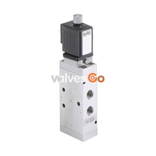
BURKERT 20127515 (Type 6519) is a servo-assisted 5/2-way pneumatic solenoid valve engineered for process automation environments requiring intrinsic safety and extended thermal resistance. Built with a 1.4571 stainless steel main body, 1.4305 stainless steel pilot stage, and polyurethane (PUR) seals, article 20127515 accommodates medium temperatures from -30 °C to +80 °C and ambient temperatures from -30 °C to +60 °C. The valve operates without continuous air consumption, minimizing control air demand while actuating double-acting pneumatic drives or process valves.
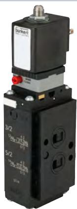
The unit is configured in circuit function H/Z (normally open state: supply port 1 communicates with working port 2, working port 4 exhausts through port 5, and exhaust port 3 remains closed). It features a 9.0 mm main valve orifice and a 0.9 mm pilot control orifice, delivering a nominal air flow rate of 1980 l/min across an operating pressure envelope of 2.0 to 10.0 bar. Process connections comprise 1/4" NPT female threads with an FM02 flange interface and a 33 mm add-on dimension. Electrical actuation is achieved via an intrinsically safe coil rated at 11.1 V DC (Coil size 5), certified according to ATEX and IECEx standards for II 2 G Ex ia IIC T6 Gb and II 2 D Ex ia IIIC T135°C Db.
| Technical Parameter | Specification Value | Standards / Notes |
|---|---|---|
| Burkert Type Family | Type 6519 | Pilot-operated directional control valve |
| Burkert Article Number | 20127515 | Specific configured execution |
| Valve Construction | Piston spool with diaphragm pilot seat | Zero continuous control air consumption |
| Number of Ports / Positions | 5 ports / 2 switching positions | Circuit function H/Z |
| Normal Position | Normally open | Port 1 connected to 2; port 4 to 5; port 3 closed |
| Main Valve Orifice (DN) | 9.0 mm | Pilot orifice: 0.9 mm |
| Flow Rate QNn (Air) | 1980 l/min | Measured at +20 °C, 6 bar inlet, 1 bar Δp |
| Working & Supply Connections | 1/4" NPT female thread | Supply side flanged (FM02 interface) |
| Auxiliary Pilot Port | M5 thread | For external pilot air supply if applicable |
| Main Valve Body Material | Stainless steel 1.4571 | High chemical and atmospheric resistance |
| Pilot Valve Body Material | Stainless steel 1.4305 | Resistant to outdoor exposure |
| Sealing Material | PUR (Polyurethane), NBR, FKM | Suitable for extended temperature range |
| Operating Pressure Range | 2.0 to 10.0 bar | Minimum differential pressure: 2.0 bar |
| Medium Temperature Range | -30 °C to +80 °C | Lubricated or non-lubricated compressed air |
| Ambient Temperature Range | -30 °C to +60 °C | Valid for coil size 5 Ex ia execution |
| Switching Times | Opening: 12 ms, Closing: 74 ms | Stainless steel 5/2-way response profile |
| Return Mechanism | Pneumatic spring + mechanical spring | Defined return into safe unpowered state |
| Manual Override | No manual override | Direct electrical pilot switching only |
| Add-On Dimension | 33 mm | Valve pitch dimension |
| Ingress Protection Class | IP65 | With correctly mounted Form A plug connector |
Type 6519 utilizes a servo-assisted design combining an intrinsically safe electromagnetic pilot stage with a diaphragm-actuated main piston spool. The diaphragm-controlled valve seats operate with minimal internal friction, ensuring positive switching performance even after prolonged stationary periods or in cold outdoor operating environments.
In circuit function H, pressure applied at supply port 1 directs air to working port 2 while exhaust air from port 4 vents through exhaust port 5. When the solenoid is de-energized, the internal pneumatic and mechanical return springs immediately restore the valve to its normal position without relying on continuous pilot bleed.
Operating Compressed Air Quality
Compressed air must comply with ISO 8573-1:2010 Class 7.2.4. To prevent ice formation from expanding air inside the pilot and spool chambers, the pressure dew point must remain at least 10 K below the actual medium temperature.
For systems requiring external pilot pressure, pilot air must be connected to port 12 or 14 at a minimum of 70% of the working pressure applied to port 1, with an absolute minimum pilot pressure of 2.5 bar.
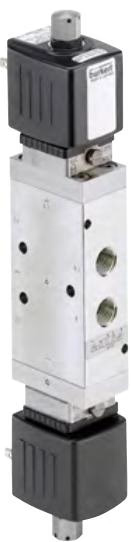
Article 20127515 incorporates an intrinsically safe solenoid coil (Coil size 5) configured for hazardous area duty. The coil interfaces via standard plug contacts conforming to DIN EN 175301-803 Form A. It is designed for operation from 24 V DC automation outputs via an associated intrinsically safe barrier or galvanic isolating module.
| Electrical & Safety Parameter | Value at +20 °C | Value at +55 °C | Standard / Conditions |
|---|---|---|---|
| Rated Operating Voltage | 11.1 V DC | 11.1 V DC | Nominal coil rating |
| Minimum Terminal Voltage | 9.0 V | 10.4 V | Threshold for reliable pull-in |
| Minimum Switching Current | 29 mA | 29 mA | Threshold for reliable pull-in |
| Nominal Coil Resistance | 310 Ω | 360 Ω | Coil size 5 winding |
| Maximum Input Voltage (Ui) | 35 V | — | Safety limit specification |
| Maximum Input Current (Ii) | 0.9 A | — | Safety limit specification |
| Maximum Input Power (Pi) | 1.1 W | — | Safety limit specification |
| Voltage Tolerance | ±10% | ±10% | Permissible supply deviation |
| Duty Cycle | 100% ED | 100% ED | Continuous operation rated |
| ATEX Explosion Protection | EPS 18 ATEX 1 088 X | II 2 G Ex ia IIC T6/T4 Gb; II 2 D Ex ia IIIC T135 °C Db | |
| IECEx Explosion Protection | IECEx EPS 18.0038X | Ex ia IIC T6/T4 Gb; Ex ia IIIC T135 °C Db |
Hazardous Location Operating Conditions
The valve must be operated strictly within the approved electrical safety thresholds (Ui ≤ 35 V, Ii ≤ 0.9 A, Pi ≤ 1.1 W) using an approved intrinsic safety barrier. The maximum medium temperature must never exceed the temperature rating of the applicable class minus 5 K (for T6: +85 °C - 5 K = +80 °C).
The wetted and environment-contacting components of article 20127515 are fabricated from high-grade austenitic stainless steel. The main valve body is manufactured from 1.4571 (316Ti) stainless steel, providing high durability against atmospheric moisture and chemical washdown. The pilot valve housing is constructed from 1.4305 stainless steel.
Internal seals are composed of polyurethane (PUR) combined with NBR and FKM. PUR provides wear resistance across high-cycle operations, while maintaining elastic sealing properties down to -30 °C. Chemical compatibility for specific industrial gases and ambient atmospheres can be evaluated using the online Bürkert resistApp chart.
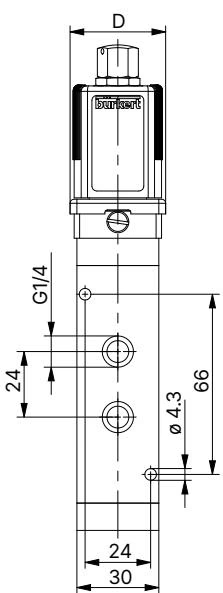
The valve body dimensions for circuit function H in stainless steel extended temperature execution are standardized as follows:
| Dimension Code | Component / Section | Value (mm) |
|---|---|---|
| A | Port centerline to reference face | 53.5 mm |
| B | Valve body base width | 107.0 mm |
| D | Ex ia pilot housing lateral offset | 40.7 mm |
| E | Ex ia pilot housing depth | 51.0 mm |
| H | Total valve assembly height (Ex ia) | 186.6 mm |
| Pitch Dimension | Add-on module dimension 1 | 33.0 mm |
All fluidic ports are indelibly numbered on the stainless steel valve body:
| Connection / Fastener | Thread Size | Recommended Torque | Maximum Permissible Torque |
|---|---|---|---|
| Fluidic port fittings | 1/4" NPT female | 4 to 7 Nm | 20 Nm |
| Auxiliary pilot port | M5 | 1.0 to 1.2 Nm | 3 Nm |
| Body wall mounting screws | M4 | 2.0 Nm | 5 Nm |
| Pilot stage fixing screws | Metric | 1.0 Nm | 1.5 Nm |
| Coil fastening nut | Metric (open-end wrench) | 4.0 Nm | 5 Nm |
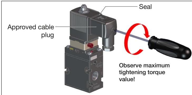
| Cable plug retaining screw | M3 (DIN EN 175301-803) | 0.8 Nm | 1.0 Nm |
Manifold Block Restriction
Type 6519 valves equipped with Ex ia intrinsically safe coils, terminal boxes, or NAMUR flange bodies are designed for direct installation and are not compatible with MP07 modular base rail manifolds.
The solenoid coil can be rotated in 4 × 90° increments to accommodate constrained field installations. To reposition the coil, loosen the fastening nut with an open-end wrench, turn the coil to the desired angle, and retighten the nut to a maximum torque of 5 Nm. Never use the solenoid as a lever arm.
When securing the DIN EN 175301-803 Form A cable plug, ensure the elastomer profile gasket is seated between the plug housing and the coil header to preserve IP65 ingress protection. The protective conductor must be connected and verified for continuity (test resistance max 0.1 Ω at 12 V / 1 A).
Article 20127515 represents the 1/4" NPT stainless steel Ex ia configuration without manual override within the extended temperature Type 6519 family.
| Article No. | Circuit Function | Orifice DN | Thread | Coil Resistance | Minimum Voltage | Pressure Range | Body Material |
|---|---|---|---|---|---|---|---|
| 20127515 | 5/2-way (H/Z) | 9.0 mm | 1/4" NPT | 310 Ω (11.1 V DC) | 9.0 V DC | 2.0 to 10.0 bar | Stainless steel 1.4571 |
| 20000888 | 5/2-way (H) manual | 9.0 mm | G 1/4 | 310 Ω (11.1 V DC) | 9.0 V DC | 3.0 to 10.0 bar | Stainless steel 1.4571 |
| 20000889 | 5/2-way impulse (Z) | 9.0 mm | G 1/4 | 310 Ω (11.1 V DC) | 9.0 V DC | 3.0 to 10.0 bar | Stainless steel 1.4571 |
Explore similar products in our catalog


