

PN16

BURKERT 20128594 (Type 8640) is an 11 mm modular pneumatic valve island with 8x 3/2-way NC function C valves, G 1/4 supply, D6 ports, P-shut-off HotSwap, and IP20 collective socket connection.
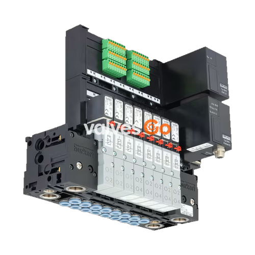
BURKERT 20128594 is a Type 8640 modular pneumatic valve island configured with eight valve slots operating in 3/2-way Circuit Function C (normally closed) on an 11 mm station pitch. Operating within a pressure range of 2.5 bar to 10.0 bar, the unit features G 1/4 central supply ports for supply channel 1 (P) and exhaust channels 3 (R) and 5 (S), alongside bottom-oriented D6 mm push-in working ports. Built to generation Revision 3 (REV3) architecture, this valve block integrates pneumatic HotSwap (integrated P-shut-off) to allow pilot valve replacement under line pressure, along with integrated non-return check valves in exhaust ports 3 and 5 to suppress backpressure surges.
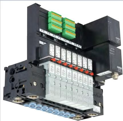
Electrical actuation is established through a parallel collective socket module utilizing screw-type terminals and looped-through ground potential. Designed for standard DIN-rail mounting inside control cabinets, the assembly carries an IP20 ingress protection rating and consumes 0.8 W per pilot valve at 24 V DC.
| Parameter | Specification |
|---|---|
| Product Type | Modular pneumatic valve island Type 8640 |
| Ident Code / SKU | 20128594 |
| Hardware Generation | Revision 3 (REV3) |
| Station Width | 11 mm per valve position |
| Number of Valve Slots | 8 stations |
| Valve Circuit Function | Circuit Function C (3/2-way, servo-controlled, normally closed) |
| Nominal Orifice | DN 4.0 mm |
| Standard Air Flow Rate ($Q_{Nn}$) | 300 l/min (measured at +20 °C, 6 bar inlet pressure, 1 bar $\Delta p$) |
| Effective Flow Rate ($Q_{Nn}$) with HotSwap | Reduced by approx. 20% (approx. 240 l/min) |
| Operating Pressure Range | 2.5 bar to 10.0 bar (overpressure to atmosphere) |
| Switching Time (ISO 12238) | Opening: 15 ms; Closing: 28 ms |
| Operating Voltage | 24 V DC (tolerance ±10%, residual ripple 1 Vss) |
| Power Consumption per Valve | 0.8 W |
| Total Current Capacity | Max. 3 A (collective connection) |
| Operating Duty Cycle | 100% continuous operation (100% ED) |
| Degree of Protection | IP20 (according to DIN EN 60529) |
| Electrical Protection Class | Class III according to VDE 0580 |
| Operating Medium | Compressed air (oil-free or lubricated, Class 7.4.4 to ISO 8573-1:2010), neutral gases (5 µm filtration recommended) |
| Medium Temperature | 0 °C to +50 °C |
| Ambient Temperature | 0 °C to +55 °C |
| Storage Temperature | -20 °C to +60 °C |
| Primary Port Sizes | Supply 1 (P), Exhaust 3 (R), Exhaust 5 (S): G 1/4 |
| Working Ports 2 (A) | Push-in connector for D6 mm tubing (bottom outlet) |
| Materials | Body: Polyamide (PA); Seals: FKM, NBR, PUR |
| Installation Method | Standard rail EN 50022 (35 x 7.5 mm or 35 x 15 mm) |
BURKERT 20128594 uses Type 6524 pilot valves consisting of a Type 6144 pilot flipper solenoid valve acting on a pneumatic seat valve body. In Circuit Function C, pressure port 1 (P) is closed and working port 2 (A) vents through exhaust port 3 (R) when de-energized. Energizing the coil directs pilot pressure onto the seat mechanism, closing port 3 and routing line pressure from port 1 to working port 2.
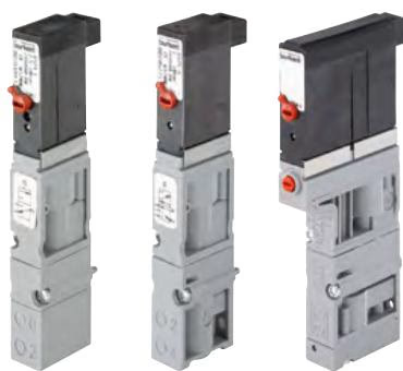
Each Type 6524 pilot valve is fitted with a mechanical manual override as standard. To actuate manually, press the override element and rotate it 90° clockwise until it locks. Manual overrides must be returned to zero position and unlocked prior to initiating electrical control.
Operating Precaution
Manual overrides must only be operated when electrical power is switched off. Engaging the manual override during electrical sequencing can cause uncoordinated machine motion.
The Revision 3 (REV3) execution incorporates standardized pneumatic flange interfaces (FM20 / FM24) and optimized channel geometry:
Control signals are routed through a parallel collective connection module equipped with screw-type terminals and looped-through ground potential.
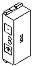
BURKERT 20128594 is composed of modular polyamide sub-bases joined via mechanical snap-fitting hooks and sealed by pre-formed elastomeric seals.
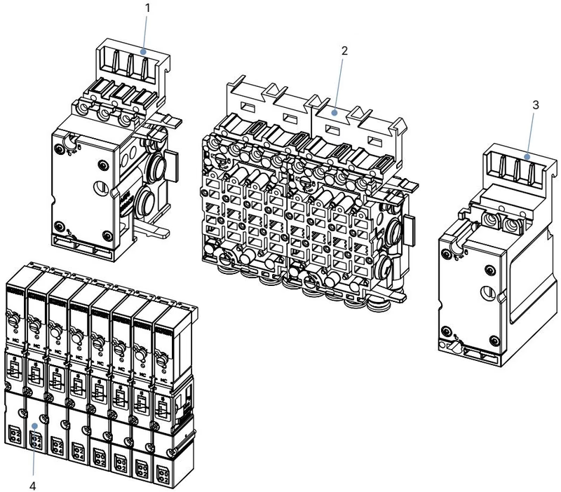
| Item | Sub-Assembly Component | Description |
|---|---|---|
| 1 | Pneumatic connection module, left | Houses main G 1/4 pneumatic ports 1 (P), 3 (R), 5 (S) |
| 2 | Basic pneumatic modules (2x 4-fold) | 11 mm pitch stations with bottom D6 push-in connectors, HotSwap, and RSV |
| 3 | Pneumatic connection module, right | Closes the pneumatic gallery; allows secondary feed or zoning if modified |
| 4 | Solenoid valves Type 6524 | 8x 3/2-way CF C pilot valves secured by M2 screws (0.6 ±0.1 Nm torque) |
Mounting is accomplished directly on DIN rails conforming to EN 50022 (35 x 7.5 mm or 35 x 15 mm). The valve island is hooked into the upper guide groove, swung downward, snapped onto the lower rail edge, and clamped with integrated mounting screws.
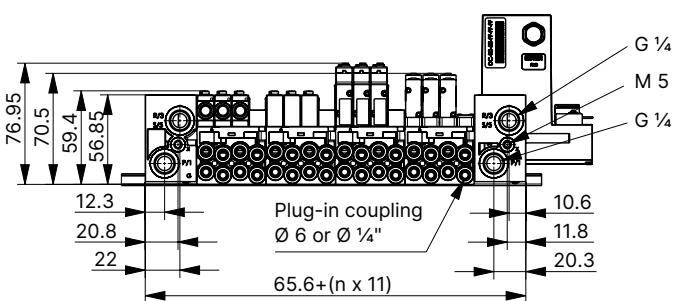
Tubing inserted into the D6 push-in fittings must comply with DIN 73378 and ISO 14743:2020:
| Tubing Outer Diameter | Minimum Tensile Holding Force: Polyamide (PA) | Minimum Tensile Holding Force: Polyurethane (PU) |
|---|---|---|
| 6 mm | 120 N | 100 N |
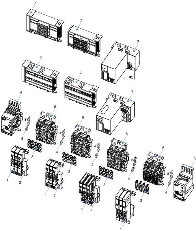
| Component Description | Specifications / Revision Compatibility | Article Number |
|---|---|---|
| Replacement Valve Type 6524 | 3/2-way CF C, 2.5...10 bar, 24 V DC, 0.8 W, REV3 (FM24 interface) | 20029918 |
| Base Unit 4-Fold (11 mm) | D6 push-in ports, HotSwap, check valves (RSV), REV3 | 20040335 |
| Supply Connection Unit, Right | 11 mm width, G 1/4 port | 20040351 |
| Supply Connection Unit, Left | 11 mm width, G 1/4 port | 20040352 |
| Valve Seal Set FM24 | 12x replacement seals for Type 6524 on REV3 base | 20024336 |
| Module Seal Set MP16 | 4x inter-module profile seals for Type 8640 REV3 | 20024339 |
| Unused Station Cover Plate | Covers pneumatic port on base module (requires electrical cover 653670) | 661092 |
| Electrical Connection Cover | Protective blind cover for unused electrical base slot | 653670 |
| Fault | Possible Cause | Corrective Action |
|---|---|---|
| Valve fails to switch | Absence of 24 V DC supply voltage or excessive voltage drop | Check collective socket screw terminals; verify 24 V DC ±10% at the coil |
| Manual override locked in manual position | Rotate manual override counter-clockwise to zero position | |
| Pilot supply pressure below 2.5 bar | Restore pressure supply to at least 2.5 bar; verify header capacity | |
| Delayed switching or blow-off at exhaust | Supply volume inadequate (pressure dip during actuation) | Increase upstream pipe diameter; clean upstream filter elements (≤ 5 µm) |
| Valves switched before pressure build-up | Apply pressure to supply port 1 (P) before sending electrical control signals | |
| Silencer blocked on exhaust ports 3 or 5 | Clean silencer or install larger expansion vessel to remove backpressure | |
| Particulate contamination inside seat valve | Blow out exhaust passages with clean compressed air; replace contaminated valve | |
| Air leakage between modules | Damaged or misaligned inter-module O-rings | Disassemble sub-blocks, verify seating of O-rings, lightly grease with compatible lubricant, and re-engage snap tabs |
| Air leakage at valve base | Crushed or missing flat seal between valve and sub-base | Install replacement FM24 seal set (20024336); torque M2 screws to 0.6 ±0.1 Nm |
Explore similar products in our catalog


