

PN16

BURKERT 20131561 Type 8640 is a modular pneumatic valve island with 11 mm station width, mixed 3/2-way valves, G 1/4 supply, D6 push-in ports, 2.5-10 bar operating pressure, and DIN rail mounting for IP20 control enclosures.
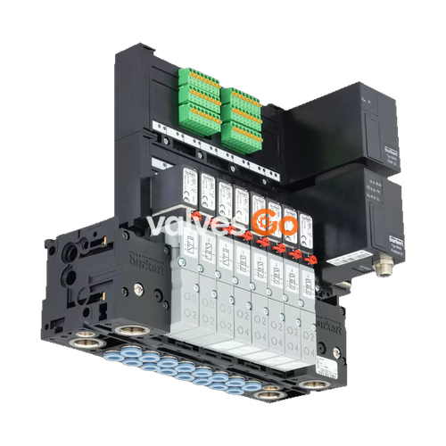
BURKERT 20131561 is a Type 8640 Generation Revision 3 (REV3) modular pneumatic valve island configured with an 11 mm station width, mixed 3/2-way valve functionality, and DIN rail mounting geometry. The unit integrates pneumatic base modules and pilot valves fabricated from high-strength polyamide, providing concentrated pilot actuation for process valves, pneumatic cylinders, and automation components in industrial control cabinets.

This specific article configuration features single electrical wiring per station without fieldbus modules, operating across an input pressure span of 2.5 bar to 10.0 bar. Pneumatic supply and exhaust headers utilize G 1/4 threaded ports, while working service lines utilize bottom-facing D6 (6 mm outer diameter) push-in tube couplings. The valve block provides an IP20 ingress rating under standard mounting and up to IP65 when enclosed in suitable control cabinets.
| Technical Parameter | Specification |
|---|---|
| Manufacturer Type | Type 8640 |
| Article Number (Ident No.) | 20131561 |
| Hardware Generation | Revision 3 (REV3) |
| Modular Station Width | 11 mm |
| Valve Population / Function | Mixed valve population (3/2-way functions) |
| Operating Pressure Range | 2.5 bar to 10.0 bar (overpressure to atmospheric) |
| Operating Medium | Oil-free or lubricated compressed dry air, neutral gases |
| Compressed Air Quality | ISO 8573-1:2010, Class 7.4.4 (5 µm pre-filtration recommended) |
| Medium Temperature | 0 °C to +50 °C |
| Ambient Operating Temperature | 0 °C to +55 °C |
| Storage Temperature | -20 °C to +60 °C (device), -40 °C to +55 °C (transport) |
| Air Supply Ports 1(P), 3(R), 5(S) | G 1/4 female thread |
| Working Ports 2(A), 4(B) | Push-in connector for hose outer diameter 6 mm (D6) |
| Working Port Exit Location | Bottom of pneumatic sub-base module |
| Nominal Air Flow Rate ($Q_{Nn}$) | 200 to 300 l/min (measured at +20 °C, 6 bar inlet, 1 bar $\Delta p$) |
| Operating Voltage | 24 V DC (±10% tolerance, 1 Vss maximum residual ripple) |
| Nominal Coil Power | 0.8 W per single valve station |
| Nominal Duty Cycle | 100% continuous operation (ED) |
| Electrical Protection Class | III according to VDE 0580 |
| Degree of Protection | IP20 (IP65 inside closed control cabinets) |
| Mounting Standard | Standard DIN rail EN 50022 (35 x 7.5 mm or 35 x 15 mm) |
| Body / Manifold Material | Polyamide (PA) |
| Sealing Materials | FKM, NBR, and PUR |
Model 20131561 belongs to the BURKERT Type 8640 REV3 production series. REV3 hardware introduces specific mechanical and pneumatic enhancements over earlier REV1 and REV2 versions:
Flange Compatibility
Replacement pilot valves and sub-base modules must correspond to the REV3 generation. Standardised single valves for REV3 cannot be directly combined with older REV1/REV2 sub-bases without appropriate interface alignment.
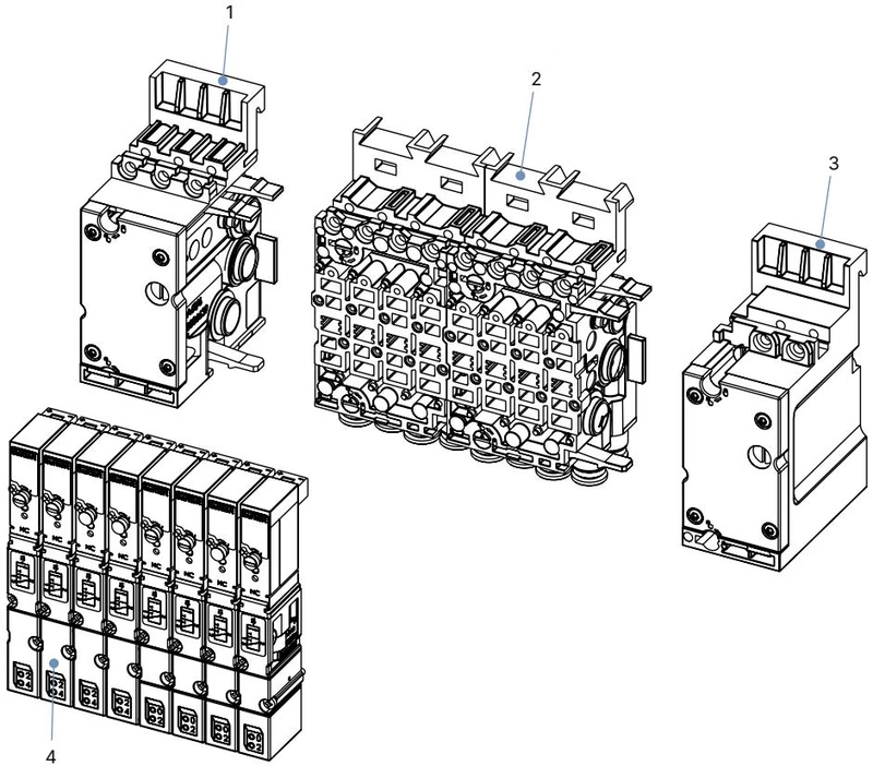
Type 8640 pneumatic assemblies are constructed from modular sub-base blocks held securely by built-in latch hooks:
| Item | Assembly Element | Technical Description |
|---|---|---|
| 1 | Left pneumatic connection module | Houses primary supply port 1(P) and exhaust port 3(R) in G 1/4 |
| 2 | Basic pneumatic modules | Multi-station blocks (e.g. 4-fold) accommodating 11 mm valves with D6 bottom ports |
| 3 | Right pneumatic connection module | Terminal supply unit or pressure zone separation module |
| 4 | Pilot valves | Type 6524 / 6525 flipper-actuated pneumatic seat valves |
Assembly of pneumatic modules proceeds from the left connection module. Inter-module sealing relies on dual O-rings lightly greased prior to mechanical engagement. Lower latch hooks snap into the preceding module's grooves before rotating upward to lock the upper tab.
Model 20131561 utilizes an 11 mm mixed configuration incorporating BURKERT Type 6524 flipper pilot solenoid valves. Each pilot valve combines a Type 6144 flipper actuator with a high-response pneumatic seat valve body:
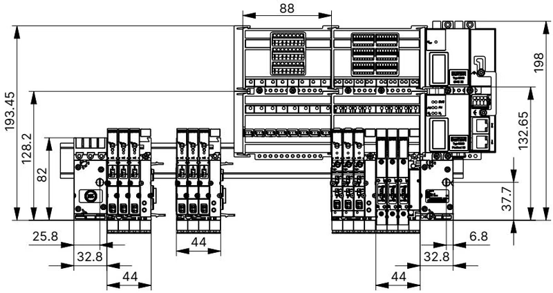
Model 20131561 is engineered for direct DIN-rail attachment inside cabinets. Any installation orientation is permissible, although mounting with solenoid coils pointing upright is recommended.
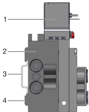
Pneumatic working lines connect via D6 push-in couplings conforming to ISO 14743:2020. Strict piping preparation prevents leakage and line separation under pressure:
| Hose Outer Diameter (OD) | Polyamide (PA) Tolerance | Polyurethane (PU) Tolerance | PA Min. Tensile Force | PU Min. Tensile Force |
|---|---|---|---|---|
| 3 mm (1/8") | ±0.08 mm | ±0.10 mm | 60 N | 25 N |
| 4 mm (5/32") | ±0.08 mm | ±0.10 mm | 70 N | 50 N |
| 6 mm (1/4") | ±0.08 mm | ±0.10 mm | 120 N | 100 N |
| 8 mm (5/16") | ±0.08 mm | ±0.10 mm | 170 N | 150 N |
| 10 mm (3/8") | ±0.08 mm | ±0.15 mm | 250 N | 200 N |
| 12 mm (1/2") | ±0.10 mm | ±0.15 mm | 300 N | 200 N |
Tubing Retention
For 6 mm lines, a minimum tensile resistance of 120 N (for PA) and 100 N (for PU) must be maintained after insertion. When using softer PU tubing in vibrating applications, inserting internal support sleeves (Ident No. 20099400) provides extra mechanical stability.
When threading pneumatic fittings into the Type 8640 supply or working ports, adhere to the recommended torque limits to prevent stress cracking in the polyamide manifolds:
| Port Thread Size | Port Function | Recommended Torque | Maximum Permissible Torque |
|---|---|---|---|
| G 1/4 / NPT 1/4 | Supply / Exhaust Ports 1(P), 3(R), 5(S) | 4 to 7 Nm | 20 Nm |
| G 1/8 / NPT 1/8 | Working Ports 2(A), 4(B) | 3 to 6 Nm | 7 Nm |
Manifold Protection
Never use the solenoid coil or valve body as a lever when tightening threaded pipe fittings. Threaded connections must be sealed using PTFE tape or compatible elastomer thread seals.
| Operational Malfunction | Potential Cause | Remedial Action |
|---|---|---|
| Valves fail to actuate | Operating voltage absent or below tolerance | Verify 24 V DC supply and check polarity on coil terminals. |
| Manual override locked in actuated position | Turn manual override 90° counterclockwise back to zero position. | |
| Supply pressure insufficient (< 2.5 bar) | Confirm supply volume; verify main pressure is within 2.5 to 10.0 bar. | |
| Delayed valve switching or blow-off at exhaust | Supply pressure below required operating limit | Ensure upstream regulators, filters, and lines provide adequate volume. |
| Valve de-energized during initial pressure rise | Apply full pneumatic pressure before issuing electrical control signals. | |
| Exhaust restriction or clogged silencers | Clean contaminated silencer inserts or install larger exhaust headers. | |
| Contamination in pilot seat or core | Pulse-blow pneumatic exhaust channels or replace defective valve module. | |
| External leakage between modules | O-ring seals pinched, damaged, or omitted | Disassemble block, inspect module O-rings, re-lubricate and reseat. |
| Flange seals displaced under valve body | Ensure 3 O-rings/profile seals sit properly in valve base recesses. |
| Component Description | Generation / Interface | Article Number |
|---|---|---|
| Type 6524 3/2-way NC Valve (2.5-10 bar, 24 V DC) | REV3, 11 mm station width | 20029918 |
| Type 6524 3/2-way NO Valve (2.5-10 bar, 24 V DC) | REV3, 11 mm station width | 20029919 |
| Type 6525 5/2-way Valve (2.5-10 bar, 24 V DC) | REV3, 11 mm station width | 20029920 |
| Type 6524 2 x 3/2-way NC Valve (2.5-10 bar, 24 V DC) | REV3, 11 mm station width | 186260 |
| Pneumatic Supply Unit Right, G 1/4 | Type 8640 REV3, 11 mm | 20040351 |
| Pneumatic Supply Unit Left, G 1/4 | Type 8640 REV3, 11 mm | 20040352 |
| Pneumatic Base Unit 4-fold, D6, FM20 | Type 8640 REV3, 11 mm | 20040334 |
| Set of Module Seals (MP16) | Type 8640 REV3, 11 mm (4 pcs) | 20024339 |
| Set of Valve Seals (FM20) for Type 6524 2x 3/2-way | Type 8640 REV3 (12 pcs) | 20016305 |
| Set of Valve Seals (FM24) for Type 6524 | Type 8640 REV3 (12 pcs) | 20024336 |
| Blanking / Cover Plate for 11 mm Valve Slot | Solenoid valves Type 6524/6525 | 661092 |
Explore similar products in our catalog


