

PN16

Burkert 20132441 Type 8652 AirLINE valve island features 16 slots, 15x 2x 3/2-way NC valves, 1 blind plate, D10/D6 brass ports, aluminium AirLINE Quick base, and multi-protocol Industrial Ethernet.
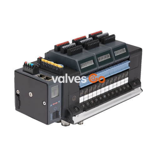
BURKERT 20132441 Type 8652 AirLINE is a 16-slot electropneumatic valve island pre-configured for automated process environments. The unit integrates 15 dual 3/2-way normally closed solenoid valve slices (Circuit Function C) and 1 blind plate on an anodised aluminium AirLINE Quick base plate. Pneumatic connections comprise push-in D10 mm brass fittings for main supply port 1 and push-in D6 mm brass fittings for working ports 2 and 4. Operating under an internal auxiliary pilot air supply from 3 bar to 10 bar, the system handles process pressures from vacuum (-1.00 bar) up to 10.00 bar across an operating temperature range of -10 °C to +55 °C.
Communication is managed via an integrated ME43 fieldbus gateway executing multi-protocol Industrial Ethernet (PROFINET IO, EtherNet/IP, Modbus TCP, EtherCAT, and CC-Link IE Field Basic) through dual RJ45 Ethernet ports (X1 and X2). The valve island is built in the Basic variant without an integrated LC display or digital input modules. It incorporates a pneumatic intermediate feed module to maintain uniform pilot and main line pressure along the 16-slot rail.
| Parameter | Specification |
|---|---|
| Type | 8652 AirLINE |
| Article Number (Ident) | 20132441 |
| Total Valve Slots | 16 slots |
| Installed Valve Hardware | Slots 1 to 15: Type 6534 2x 3/2-way CF C (NC); Slot 16: Blind plate |
| Controlled Valve Functions | 30 active pilot channels (15 dual valves) + 1 blanking position |
| Pilot Valve Mechanism | Integrated Type 6164 pilot solenoids |
| Operating Pressure Range | -1.00 bar to 10.00 bar (vacuum to 10 bar) |
| Auxiliary Pilot Air Pressure | 3 bar to 10 bar (internal pilot feed) |
| Flow Rate $Q_{Nn}$ (Air) | 310 l/min (measured at +20 °C, 6 bar inlet, 1 bar differential pressure) |
| Intermediate Supply Feed | 1 PCE intermediate module included |
| Operating Medium | Lubricated or oil-free dry compressed air, neutral gases (ISO 8573-1:2010, Class 7.4.4; 5 µm filtration recommended) |
| Operating Voltage | 24 V DC (±10%), residual ripple 1 Vss |
| Power Consumption per Valve | 0.7 W nominal (drops to 0.175 W after electronic power reduction) |
| Current Consumption per Valve | 29 mA nominal (drops to 10 mA after electronic power reduction) |
| Electrical Protection Class | Class III according to DIN EN 61140, VDE 0140 |
| Degree of Protection | IP20 standalone; IP65 inside closed control cabinet with AirLINE Quick |
| AirLINE Quick Material | Anodised aluminium adapter plate, nickel-plated brass tube fittings |
| Pneumatic Supply / Exhaust Ports | Push-in connector D10 mm (Port 1 / Exhaust 3, 5) |
| Pneumatic Working Ports | Push-in connector D6 mm (Ports 2 and 4) |
| Ambient and Medium Temperature | -10 °C to +55 °C |
| Storage Temperature | -20 °C to +60 °C |
| Operating Duty Cycle | 100% continuous duty (ED) |
| Switching Time | Measured according to ISO 12238 (Opening: 15 ms; Closing: 15 ms) |
Article 20132441 is populated with 15 valve slices of Circuit Function C (CF C) and 1 blind plate slice. Each CF C slice contains two independent 3/2-way servo-assisted solenoid valves that remain closed in the unpowered state (normally closed). Actuation is supported by manual overrides with latching detents. Unused slot 16 is fitted with a Type 6534 blind plate to preserve manifold pressure containment.
| Station | Hardware Component | Circuit Function | Function Description |
|---|---|---|---|
| Positions 1–15 | Type 6534 Solenoid Valve | 2x 3/2-way CF C | Servo-assisted, normally closed, unpowered closed, latching manual override |
| Position 16 | Type 6534 Blind Plate | Dummy position | Isolates pneumatic channels; allows future valve retrofitting |
Pilot Air Routing
Article 20132441 utilizes internal auxiliary pilot air. The pilot supply branches internally from main supply port 1. The main line pressure must remain at or above 3 bar (up to 10 bar) to ensure reliable servo switching of the pilot stages.
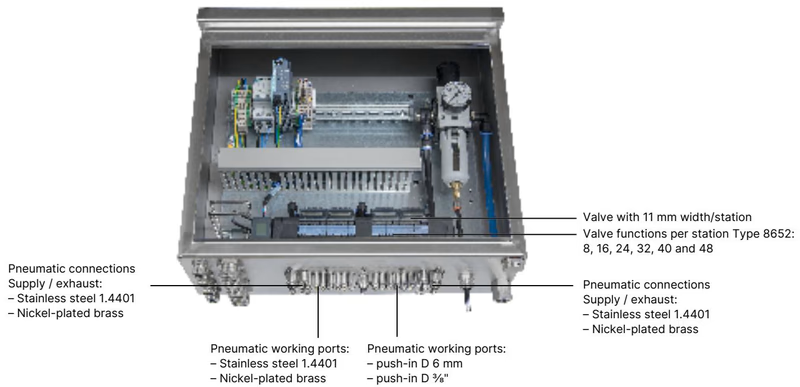
The valve island is factory-fitted with an AirLINE Quick adapter plate manufactured from anodised aluminium. This interface mounts directly into a cutout in the floor or wall of the control cabinet, placing pneumatic push-in fittings on the cabinet exterior.
| Feature | Parameter |
|---|---|
| Adapter Plate Material | Anodised aluminium (Alu) |
| Tube Fitting Material | Nickel-plated brass |
| Supply Port Dimension | Push-in D10 mm (Port 1) |
| Working Port Dimension | Push-in D6 mm (Ports 2 and 4) |
| Ingress Protection | IP65 inside closed cabinet; IP20 at interior electrical modules |
| Mounting Fasteners | 10x M5 screws (DIN 6912 M5x10 A2) |
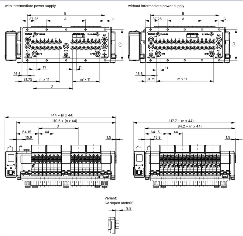
Dimensions for 16-, 20-, and 24-slot variants with and without the intermediate supply module conform to standardized hole pitch intervals:
| Variant | A (mm) | B (mm) | C (Fasteners) | D (mm) | m | m' | n |
|---|---|---|---|---|---|---|---|
| 16-fold with intermediate supply (20132441) | 112 | 224 | 10 x M5 | 114.3 | 7 | 7 | 4 |
| 20-fold with intermediate supply | 134 | 268 | 10 x M5 | 158.3 | 11 | 7 | 5 |
| 24-fold with intermediate supply | 156 | 312 | 10 x M5 | 158.3 | 11 | 11 | 6 |
| 16-fold without intermediate supply | 99 | 198 | 10 x M5 | — | 15 | — | 4 |
| 20-fold without intermediate supply | 121 | 242 | 10 x M5 | — | 19 | — | 5 |
| 24-fold without intermediate supply | 143 | 286 | 10 x M5 | — | 23 | — | 6 |
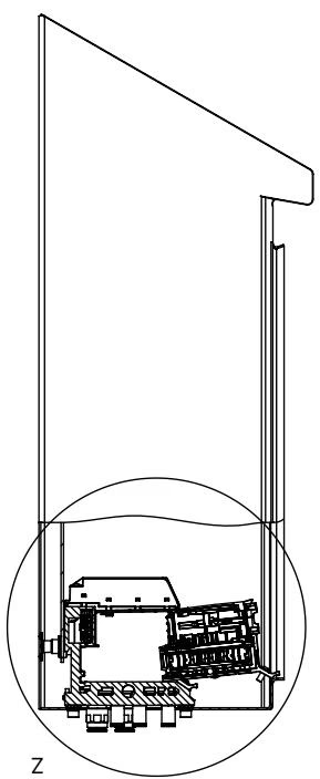
Maintain adequate clearance between the rear wall and front edge of the control cabinet during installation. This spacing preserves airflow and provides physical access to pneumatic connections and electrical plugs during maintenance.
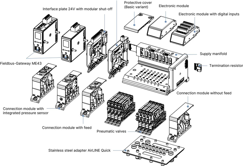
Type 8652 utilizes an electrical interface plate with isolated terminals for electronic logic and pneumatic valve coils.
| Terminal | Wire Colour | Signal Assignment |
|---|---|---|
| 1 | Red | 24 V DC (Electronics / Logic Supply) |
| 2 | White | CAN_H (büS interface) |
| 3 | Green | Shielding |
| 4 | Blue | CAN_L (büS interface) |
| 5 | Black | GND (0 V DC) |
Permissible wire cross-section: ≤ 1.5 mm².
| Clip | Wire Colour | Signal Assignment |
|---|---|---|
| 1 | Red | AUX 24 V DC (Valve Coil Supply) |
| 2 | Black | GND (0 V DC) |
Power Separation
The electronic communication logic and pneumatic valve coils must be supplied from galvanically separated or independently fused power lines to prevent field interference from resetting communication modules during coil actuation.
Dual RJ45 Ethernet ports allow line, star, or ring network topologies via integrated switching:
| Pin | Signal | Description |
|---|---|---|
| 1 | TX+ | Transmit Data + |
| 2 | TX- | Transmit Data - |
| 3 | RX+ | Receive Data + |
| 4 | N.C. | Not connected |
| 5 | N.C. | Not connected |
| 6 | RX- | Receive Data - |
| 7 | N.C. | Not connected |
| 8 | N.C. | Not connected |
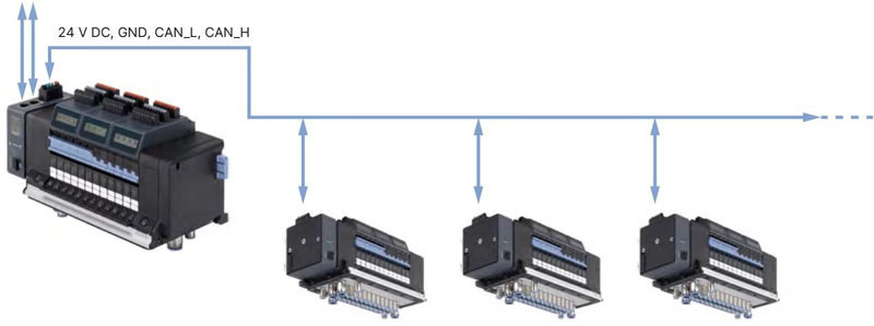
Type 8652 with Industrial Ethernet functions as a fieldbus master or slave node on PROFINET IO, EtherNet/IP, Modbus TCP, EtherCAT, or CC-Link IE Field Basic networks. Subordinate Bürkert büS field devices connect downstream in an integrated sub-network.
When certified under code PX68 or PU17, Type 8652 carries the following hazardous area ratings:
Electrical Disconnection in Explosive Atmospheres
Do not connect or disconnect electrical spring-loaded terminals (24 V DC supply, valve auxiliary power, or digital inputs) while energized in the presence of an explosive atmosphere. De-energize all circuits prior to maintenance. Hot swapping of pneumatic valves is prohibited unless the area is verified free of explosive gas or dust.
| Description | Article Number |
|---|---|
| Type 8652 Valve Island (Configured Article 20132441) | 20132441 |
| Type 6534 Replacement Valve, 2x 3/2-way CF C (NC), with screws | 301374 (Kit 296031) |
| Type 6534 Blind Plate for vacant valve slots, with screws | 335779 (Kit 327614) |
| 5-Pin Spring-Loaded Terminal Connector (Electronics / Bus Supply) | 920180 |
| 2-Pin Spring-Loaded Terminal Connector (Valve Auxiliary Supply) | 920442 |
| Type ME43 Fieldbus Gateway — Industrial Ethernet (PROFINET, EtherNet/IP, Modbus TCP, EtherCAT) | 301799 |
| AirLINE Quick Height Adapter for 16-fold with intermediate feed | 754962 |
| AirLINE Quick Retaining Plate for exterior cabinet mounting, 16-fold with intermediate feed | 60005568 |
| AirLINE Quick Cutout Blind Plate, 16-fold with intermediate feed | 754967 |
| Fastening Screw Set M5x10 A2 DIN 6912 (10 pieces) | 308661 |
| Bürkert Communicator Software | Type 8920 |
| USB büS Interface Set 1 (Type 8923) for PC connection | 772426 |
Explore similar products in our catalog


