

PN16

BURKERT 20135258 is a Type 8647 AirLINE SP electropneumatic valve island featuring 24x 3/2-way NC valves, 11 mm station width, G 1/4 supply ports, D6 working connections, HotSwap, and Siemens ET 200SP integration.
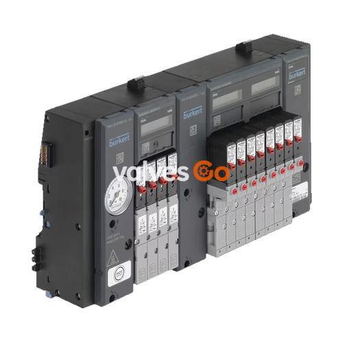
BURKERT 20135258 is an AirLINE SP Type 8647 modular electropneumatic automation system configured as a 24-bank valve island with an 11 mm station pitch. The island integrates 24 individual 3/2-way servo-controlled pilot solenoid valves in Circuit Function C (normally closed) on pneumatic base modules. Developed specifically for direct mechanical and electrical integration into the Siemens SIMATIC ET 200SP and SIMATIC ET 200SP HA distributed I/O systems, the assembly links pneumatic actuators directly to process controllers via PROFINET IO or PROFIBUS DP.
Each valve position features integrated pneumatic HotSwap functionality at port 1 (P), allowing valves to be serviced or exchanged under continuous system operating pressure. The exhaust ports 3 (R) and 5 (S) are equipped with integrated check valves (RSV) to suppress transient backpressures in shared exhaust headers. Due to the air volume requirements across 24 active valve functions, this assembly includes one factory-configured intermediate supply feed unit (PSU-M) positioned within the valve train.
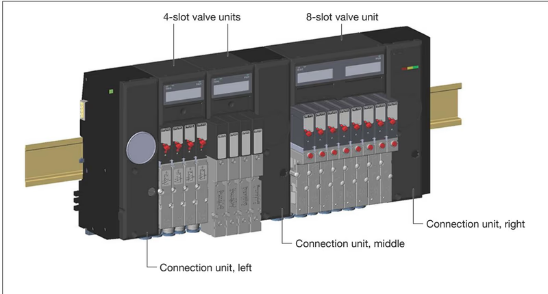
Type 8647 AirLINE SP combines Siemens distributed peripheral components and pneumatic control into a unified terminal mounted on a common standard rail. Communication and DC load power interface through the backplane bus system of SIMATIC ET 200SP / ET 200SP HA without external discrete wiring harness runs between the controller outputs and solenoid coils.
Configuration tools operate identically to native Siemens I/O:
Pneumatics (Burkert).Load Voltage Planning
The permissible load voltage tolerance for pilot valves is 24 V DC ±10%, which is narrower than standard digital I/O defined by IEC 61131-2. To prevent voltage drops across large configurations, place a light-colored Siemens BaseUnit (BU...D or BU...D/T) immediately to the left of the valve block to provide dedicated power rail feeding.
Article 20135258 is built according to Bürkert Revision 2 (REV.2) specifications. REV.2 introduces unified pneumatic interfaces across all 11 mm station platforms, optimizing channel geometries and flow dynamics.
| Technical Distinguishing Feature | Revision 1 (REV.1) | Revision 2 (REV.2 - 20135258) |
|---|---|---|
| Release Ring Color on Push-In Ports | Black | Blue |
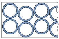
| Working Port Channel Arrangement | Parallel | Wavy (optimized air paths) |
| Flow Reduction with Integrated P Shut-Off | Up to 50% | Approximately 20% |
| Pilot Valve Flange Profile | FM14 (Single 3/2 and 5/2) / FM20 (Double) | Standardized FM20 across all 6524/6525 valves |
| Type Label Revision Marking | Without "Rev." text | Marked with "Rev.2" |
The pilot valves utilized on this island are Type 6524 Circuit Function C, combining a Type 6144 flipper solenoid armature with an elastomer-sealed poppet valve seat. Each pilot valve includes a manual override as standard, allowing manual activation during commissioning.
| Operational Parameter | Specified Value |
|---|---|
| Article Number (Ident Number) | 20135258 |
| System Type | 8647 AirLINE SP |
| Generation / Revision | Revision 2 (REV.2) |
| Number of Valve Stations | 24 stations (24 single valve functions) |
| Valve Circuit Function | Circuit Function C (3/2-way, normally closed) |
| Width per Station | 11 mm |
| Medium | Lubricated or oil-free dry compressed air, neutral gases |
| Compressed Air Quality | ISO 8573-1:2010, Class 7.4.4 (5 µm filtration recommended) |
| Operating Pressure Range | 2.5 bar to 10.0 bar (relative pressure) |
| Flow Rate (QNn value air) | 300 l/min (at +20 °C, 6 bar inlet, 1 bar pressure differential) |
| Effective Flow with P Shut-Off | Approx. 240 l/min (20% flow reduction) |
| Valve Body Material | Polyamide (PA) |
| Base Module / Enclosure Materials | Polyamide (PA), Polycarbonate (PC) |
| Seal Materials | NBR, FKM, and PUR |
| Supply Connections 1 (P), 3 (R), 5 (S) | G 1/4 female thread |
| Working Ports 2 (A) | D6 mm push-in coupling (bottom-facing orientation) |
| Auxiliary Pilot Air Port (X) | M5 female thread |
| Operating Voltage | 24 V DC (±10%, max. residual ripple 2.4 Vss) |
| Nominal Power per Coil | 0.8 W |
| Current per Valve | 40 mA nominal (28 mA holding current after 120 ms) |
| Duty Cycle | 100% ED (continuous operation) |
| Switching Times (ISO 12238) | Opening: 15 ms, Closing: 28 ms |
| Ambient Operating Temperature | 0 °C to +55 °C |
| Medium Temperature Range | 0 °C to +50 °C |
| Storage Temperature | -20 °C to +60 °C |
| Permissible Ambient Humidity | 75% average, 85% occasional (non-condensing) |
| Total System Width Limit | Max. 858 mm for standalone valve block |
| Total System Weight | Up to 10 kg depending on installed base units |
| Degree of Protection | IP20 (IP65 in closed industrial control cabinet) |
| Protection Class | Class 3 (DIN EN 61140 / VDE 0140) with FE ground rail |
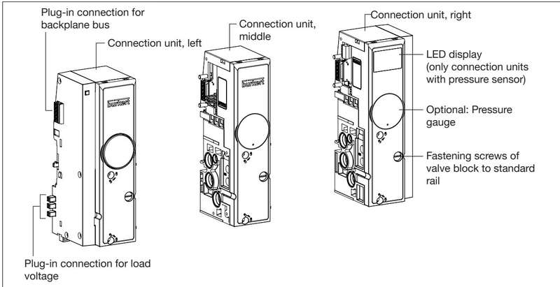
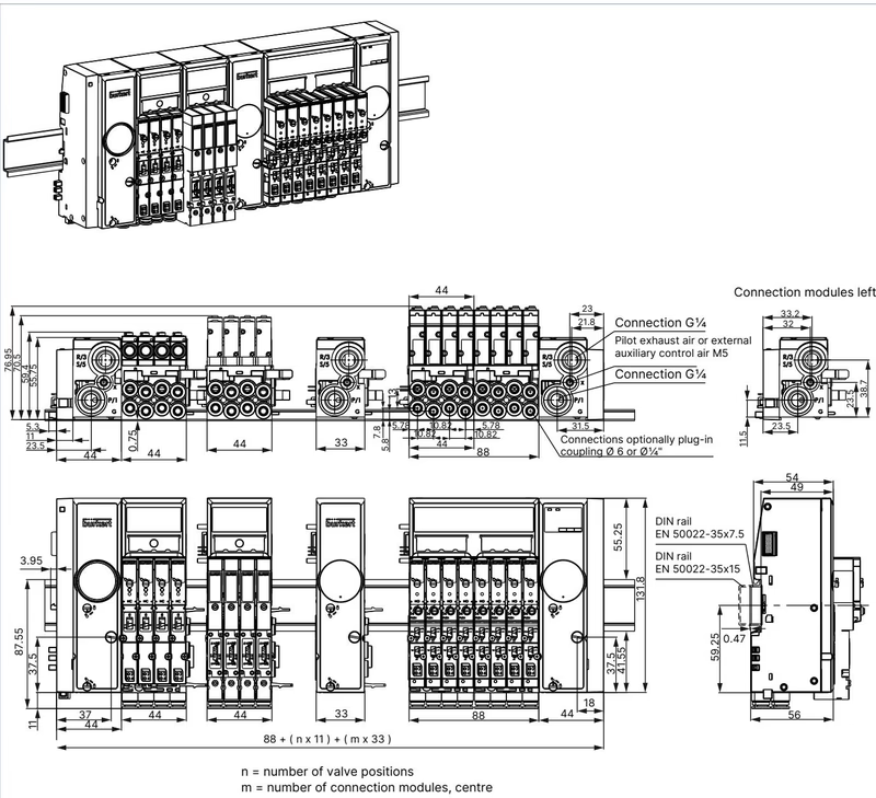
The valve block is supplied and deaerated through lateral connection units (PSU-L on the left, PSU-R on the right) and an intermediate supply module (PSU-M). The intermediate supply module is mandatory in this assembly because total air throughput exceeds single-port limits past 24 valve functions.
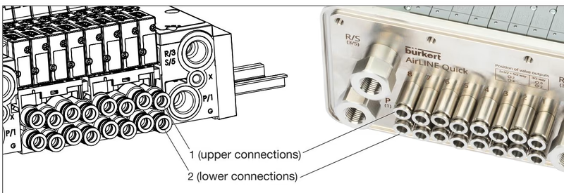
For 3/2-way single valves (Type 6524 Circuit Function C), port connections are arranged as follows:
Exhaust Air Silencing and Sizing
Ensure unrestricted exhaust venting on ports 3 (R) and 5 (S) by installing appropriately sized silencers or piping exhaust out of the cabinet. Inadequate exhaust venting generates backpressures that can cause unintended actuator movement or delayed valve shut-off.
To ensure positive sealing on D6 mm push-in connections:
Article 20135258 receives power and control logic through the electronic base modules (PQ modules). Each 4-slot or 8-slot PQ module features an LC display and front status LEDs (PWR green, DIAG red/green).
Safety Shut-Off Architecture
Electrical de-energization causes Type 6524 valves to return instantly to their normally closed rest position:
Type 8647 is supplied fully assembled and tested. Mount the terminal onto a rigid DIN standard rail (TH 35-7.5 or TH 35-15) inside an IP54 or higher industrial enclosure.
Thanks to pneumatic HotSwap shut-off seals in the 1 (P) gallery, individual valves can be replaced while the system is pressurized without interrupting operation of adjacent valves. When loosening valve retaining screws under pressure, an initial blast of air occurs until the differential shut-off element seals the base port.
Replacement Compatibility
REV.1 and REV.2 single valves are mechanically and fluidically incompatible. Always verify the flange profile before installation. Article 20135258 requires REV.2 replacement valves with FM20 flange patterns.
2002991866109265367020024336200243392002434020024341Explore similar products in our catalog


