Transit-Time Ultrasonic

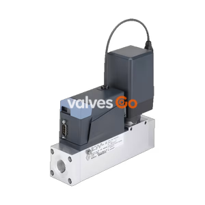
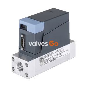
BURKERT Type 8741 Mass Flow Controller (MFC) and Meter (MFM) for gases. Features nominal flow ranges from 0.010 to 160 l/min, high accuracy, fast response times, and Industrial Ethernet, CANopen, or Modbus RTU interfaces.
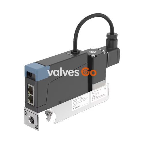
BURKERT Type 8741 mass flow controller (MFC) and mass flow meter (MFM) for gases is suitable for a variety of applications and is available with Industrial Ethernet, analogue, or fieldbus interfaces. The variant with CANopen-based Bürkert Systembus (büS) is suitable for integration into existing CANopen networks or—in combination with the Type ME43 fieldbus gateway—for integration into all common industry standards for Industrial Ethernet and/or fieldbus. The latter option is tailor-made for applications with many control loops, allowing up to 32 MFCs or MFMs to be connected to one fieldbus gateway.
Type 8741 can be configured as an MFM or an MFC according to demand. Furthermore, a Modbus RTU variant is also available. Optionally, up to four calibration curves can be stored in the device. The thermal MEMS sensor is located directly in the gas stream and therefore achieves very fast response times. As the actuator, a Bürkert direct-acting proportional valve guarantees high response sensitivity.
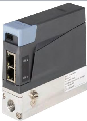
| Property | Description |
|---|---|
| Seal Material | FKM or EPDM (depending on gas) |
| Housing Material | PC (polycarbonate) |
| Base Block Material | Aluminium or stainless steel 1.4404/316L |
| Wetted Parts | Stainless steel 1.4310/302, 1.4113/434, 1.4305/303 |
| Operating Pressure | MFM: max. 25 bar; MFC: max. 25 bar (depends on medium and nominal valve size) |
| Measuring Accuracy | ±0.8% MV ±0.3% FS (under calibration conditions and after warm-up time) |
| Repeatability | ±0.1% FS |
| Turndown Ratio | 1:50, optionally 1:100 |
| Settling/Response Time | < 300 ms |
| Operating Voltage | 24 V DC (±10% tolerance, ±2% residual ripple) |
| Power Consumption | 1...3 W (as MFM); Max. 3...19.5 W (as MFC, depending on proportional valve) |
| Operating Medium | Neutral, pure gases (others on request) |
| Medium Temperature | -10 °C...+70 °C (-10 °C...+60 °C with oxygen) |
| Ambient Temperature | -10 °C...+50 °C |
| Degree of Protection | IP20 |
Conformity Standards
In accordance with the Declaration of Conformity, the product is compliant with the EU Directives. The applied standards which are used to demonstrate compliance are listed in the EU-Type Examination Certificate and/or the EU Declaration of Conformity.
Note
All values refer to 1.013 bar abs and 273.15 K (0 °C) (Index N). Other gases and gas mixtures are possible on request.
| Gas | Min. QN [l/min] | Max. QN [l/min] |
|---|---|---|
| Acetylene | 0.01 | 65 |
| Helium | 0.01 | 1000 |
| Carbon dioxide | 0.02 | 80 |
| Air | 0.01 | 160 |
| Methane | 0.01 | 160 |
| Oxygen | 0.01 | 160 |
| Nitrogen | 0.01 | 160 |
| Hydrogen | 0.01 | 1000 |
| Propane | 0.03 | 44 |
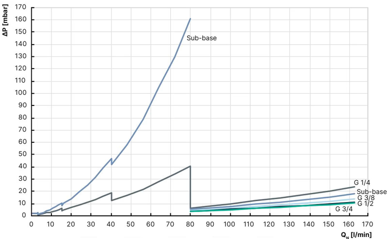
The diagram shows an example of the pressure loss curves with air flowing through. To determine the pressure loss of other gases, the corresponding air equivalent must first be calculated and the base block used for the other gas must be taken into account.
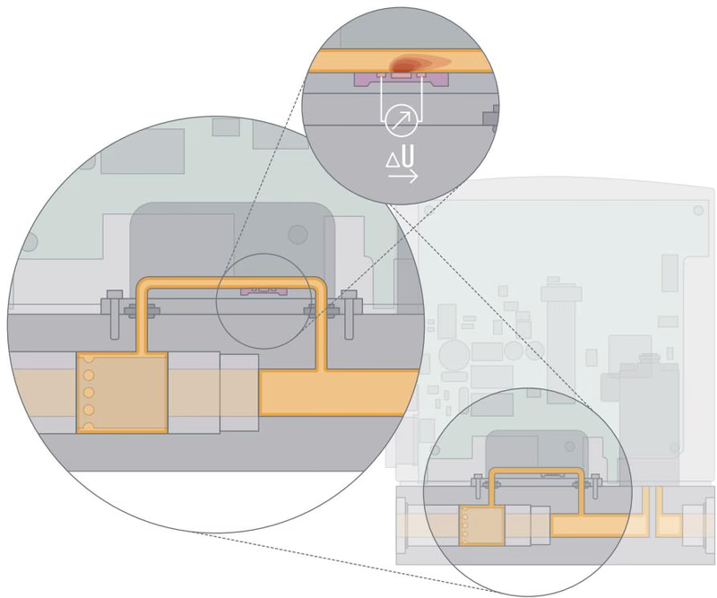
The measured values are recorded in a secondary channel. A laminar flow element in the main channel creates a slight pressure drop. A part of the gas flow is thereby directed into the secondary channel. The sensor located there records the mass flow as a temperature difference. The measurement is performed in a specially shaped flow channel whose wall contains a silicon chip with an etched membrane. A heating resistor and 2 temperature sensors, one upstream and one downstream, are attached on this membrane.
If the heating resistor is fed with a constant voltage, the differential voltage of the temperature sensors indicates the flow rate of the gas flowing over the chip.
Explore similar products in our catalog