


Up to 99.8% Efficiency

BURKERT 20143567 Type 3361 is an electromotive 2-way globe control valve with AG3 actuator (10000 N), DN 65 welded ends, PEEK seat, 24 V DC supply, PN25 rating, and equal percentage 50:1 flow characteristic.
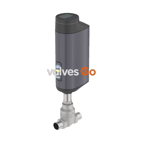
BURKERT 20143567 (Type 3361) is an electromotive 2-way globe control valve engineered for continuous flow regulation in industrial and hygienic processes. The assembly integrates a stainless steel globe valve body with an AG3 electromotive linear actuator capable of exerting 10000 N driving force. Configured with DN 65 (NPS 2 1/2) welded port connections conforming to DIN EN ISO 1127 / ISO 4200 / DIN 11866 Series B (76.1 x 2.3 mm), the valve operates across a nominal pressure span from 0 bar to 25 bar (PN 25 / Class 150) and handles media temperatures ranging from -10 °C to +185 °C.
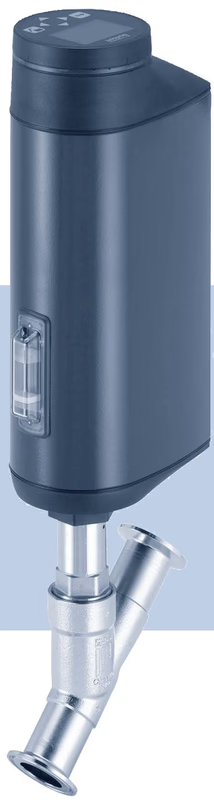
The internal trim features a 65 mm seat diameter and an equal percentage (50:1) control cone delivering a water flow coefficient Kv of 62 m³/h (Cv 71.7 gpm) under flow-below-seat orientation. Sealing at the seat is maintained by high-performance PEEK (Polyetheretherketone), compliant with food contact requirements under Regulation (EC) 1935/2004. Powered by 24 V DC, the valve features a static position blocking function without electrical energy storage, maintaining its mechanical position upon power interruption. Operator controls and interfaces comprise an analogue control unit, internal push buttons under a blind dummy cover, Service-büS digital diagnostics, and an electrical MP multipole terminal providing 1 analogue input, 1 digital input, 1 analogue output, and 2 digital outputs.
| Parameter | Value |
|---|---|
| Model (Order Number / SKU) | 20143567 |
| Type Family | 3361 |
| Valve Construction | 2-way electromotive globe control valve |
| Port Diameter | DN 65 (NPS 2 1/2) - tube dimension 76.1 x 2.3 mm |
| Connection Standard | DIN EN ISO 1127 / ISO 4200 / DIN 11866 Series B |
| Port Connection Type | Welded |
| Nominal Operating Pressure | 0 to 25 bar (PN 25, Class 150) |
| Medium Temperature Range | -10 °C to +185 °C |
| Minimum Ambient Temperature | -25 °C |
| Flow Capacity | Kv 62 m³/h (water) / Cv 71.7 gpm |
| Flow Characteristic | Equal percentage 50 : 1 |
| Flow Direction | Below seat |
| Seat Diameter | 65 mm (2 1/2") |
| Seat Seal Material | PEEK (Polyetheretherketone) |
| Valve Body Material | Stainless steel |
| Actuator Housing Materials | Powder-coated aluminium and polycarbonate (PC) |
| Driving Force | AG3 (10000 N) |
| Operating Voltage | 24 V DC |
| Typical Closing Time | 12.000 ms |
| Control Function | Blocking of static position (no internal energy storage) |
| Control Interface | Internal push buttons under dummy cover (no display module) |
| Communication Protocol | Service-büS |
| Inputs / Outputs | 1 analogue in, 1 digital in, 1 analogue out, 2 digital out |
| Degree of Protection | IP65 / IP67, NEMA 4X (with matching connections) |
| Food Safety Conformity | (EC) 1935/2004 compliant according to manufacturer declaration |
Burkert Type 3361 modular design allows component servicing and targeted spare parts replacement. Replaceable wear items comprise the control cone set, the valve seat assembly, the spindle packing gland seal set, and the spindle guide.
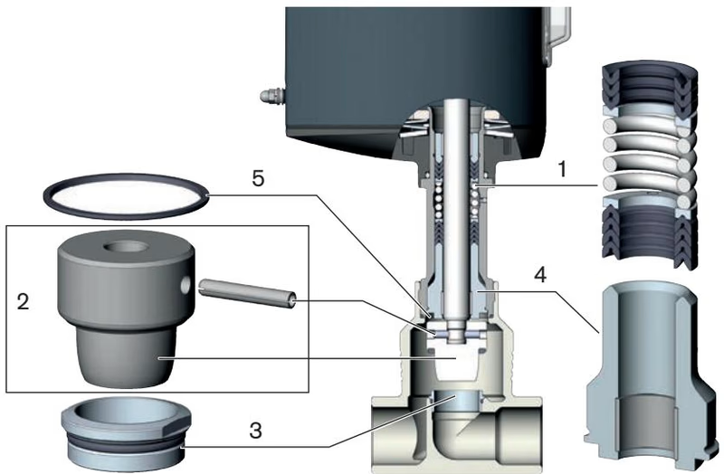
| Item | Component Description |
|---|---|
| 1 | Packing gland seal package |
| 2 | Control cone with dowel pin |
| 3 | Valve seat (with O-ring from seat size 25) |
| 4 | Spindle guide |
| 5 | Graphite seal |
For seat replacement on DN 65 valves, dedicated installation tool order number 655562 is required to engage and torque the seat inside the stainless steel body.
Operating modes and manual movements can be carried out electrically via internal buttons or mechanically without electrical power.
Because this unit does not incorporate an exterior display module, manual mode selection and electrical positioning are configured beneath the rotatable dummy cover:
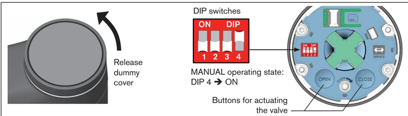
When electrical power is unavailable or disconnected during servicing, the actuator spindle can be repositioned mechanically:
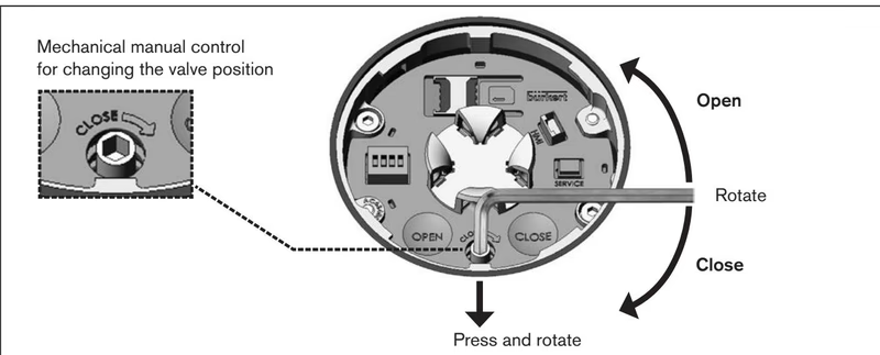
Mechanical Manual Override Torque Limit
The mechanical manual override must be actuated only when the supply voltage is switched off. Do not exceed the maximum torque limit of 2 Nm at the end positions to prevent permanent damage to the mechanical manual control mechanism.
When replacing internal trim, servicing the packing gland, or inspecting the PEEK valve seat, the actuator must be separated from the body under controlled conditions.
Residual High Pressure Hazard
Before opening lines or loosening the actuator, de-pressurize the fluid pipeline completely, drain the media, and switch off the electrical power supply.
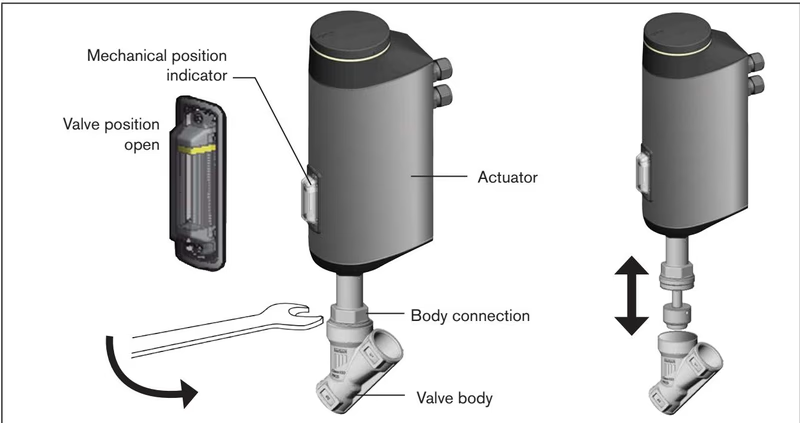
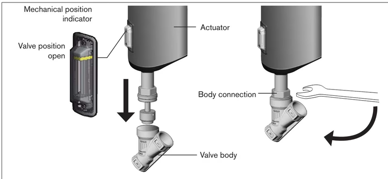
| Valve Body Orifice [DN] | Tightening Torque [Nm] | Tightening Torque [lbf ft] |
|---|---|---|
| DN 10 / DN 15 | 45 ± 3 | 33 ± 2 |
| DN 20 | 50 ± 3 | 37 ± 2 |
| DN 25 | 60 ± 3 | 44 ± 2 |
| DN 32 | 65 ± 3 | 48 ± 2 |
| DN 40 | 65 ± 3 | 48 ± 2 |
| DN 50 | 70 ± 3 | 52 ± 2 |
| DN 65 (Resource Model) | 100 ± 3 | 74 ± 2 |
| DN 80 | 120 ± 5 | 89 ± 2 |
| DN 100 | 150 ± 5 | 111 ± 2 |
Following reassembly of the actuator or replacement of the seat/cone, the physical stroke limits must be recalibrated by initiating the X.TUNE routine.
Process Isolation During X.TUNE
Never initiate X.TUNE while medium pressure is applied to the valve. Running X.TUNE under line pressure causes inaccurate stroke calibration and leads to uncontrolled process conditions.
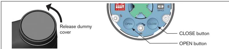
Alternatively, X.TUNE can be executed digitally via the büS Service interface using Bürkert Communicator PC software, selecting PEEK as the seat material under the calibration submenu.
| Cancellation Message / Fault Condition | Root Cause Description |
|---|---|
| Device error detected | An internal active error prevents X.TUNE execution |
| Time limit exceeded | Calibration could not complete within the maximum programmed cycle limit |
| Motor current too high | Operating current exceeded permissible drive limits during stroke detection |
| Lower end position not detected | The lower seat contact could not be recognized by the position measurement sensor |
Routine maintenance involves checking the relief bore on the packing gland for fluid leakage. Leaking fluid indicates packing gland wear requiring seal set replacement.
When assembling threaded parts or packing components, use only manufacturer-specified lubricants:
For storage prior to installation, maintain the device in a dry, dust-free environment within the ambient storage temperature range of -40 °C to +70 °C.
Explore similar products in our catalog


