

PN16

BURKERT 20149423 Type 8640 is a modular pneumatic valve island featuring 16.5 mm station width, G 3/8 supply, D8 bottom ports, collective socket module, 2-10 bar operating pressure, and IP20 protection.
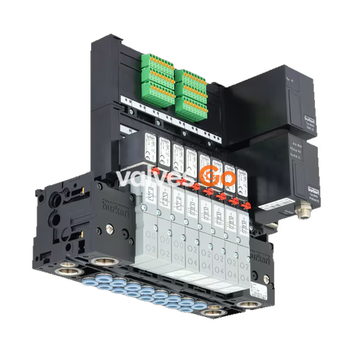
BURKERT 20149423 (Type 8640) is a revision 3 modular pneumatic valve island configured with a 16.5 mm station pitch, a G 3/8 pneumatic supply port, and bottom-facing D8 push-in working connections. Built around Type 5470 pilot-controlled directional valves and Type 6106 flipper pilot stages, this assembly provides automated pilot control for neutral media and filtered compressed air. The unit incorporates a collective socket electrical interface for integrated multichannel actuation, DIN-rail mounting hardware, and an overall enclosure rating of IP20.
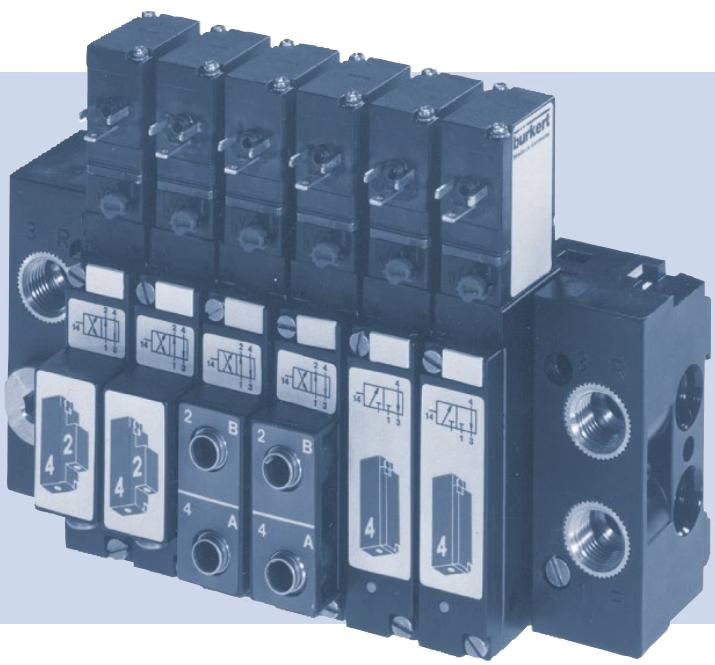
The table below outlines the core product specifications and operational constraints for article 20149423:
| Specification Parameter | Value / Characteristic |
|---|---|
| Article Number (SKU) | 20149423 |
| Product Type | Type 8640 |
| Hardware Generation | Revision 3 |
| Station Pitch (Width per Station) | 16.5 mm |
| Valve Configuration | Mixed valve population (3/2-way operation) |
| Pneumatic Supply Connection (Port 1 / P) | G 3/8 internal thread |
| Working Connection Size (Ports 2 / B and 4 / A) | D8 push-in fittings |
| Working Connection Exit Orientation | Bottom (pneumatic base module) |
| Nominal Operating Pressure Range | 2.0 bar to 10.0 bar |
| Medium Operating Temperature Range | 0.0 °C to +50.0 °C |
| Permissible Ambient Temperature Range | 0.0 °C to +55.0 °C |
| Digital Input Channels | 0 PCE |
| Integrated Pressure Sensor | None (0) |
| Integrated Exhaust Check Valves | Not present (Ports 3/R and 5/S) |
| Pneumatic HotSwap Function | Not present (Port 1/P) |
| Communication / Wiring Module | Collective socket module |
| Internal Control Bus | Bürkert proprietary |
| Ingress Protection Rating | IP20 (with appropriate electrical mating connection) |
| Mechanical Installation Method | Standard DIN rail mounting |
Individual valve slices in the Type 8640 island utilize Type 5470 directional bodies coupled to Type 6106 electromagnetic pilot valves. Sealing within the main stage is handled by NBR diaphragm and seat seals mounted between connection plates.
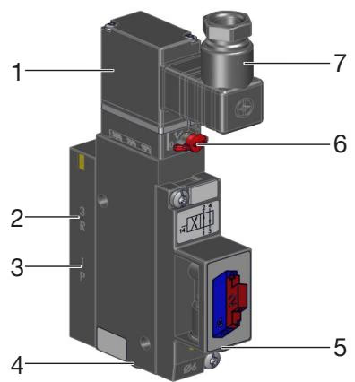
| Item | Designation |
|---|---|
| 1 | Pilot valve Type 6106 |
| 2 | Exhaust port 3 (R) |
| 3 | Pressure port 1 (P) |
| 4 | Working port 4 (A) |
| 5 | Working port 2 (B) |
| 6 | Manual override mechanism |
| 7 | Cable plug interface (Type 2506 / 2516 reference) |
Pneumatic fluid channels are identified numerically across the sub-base and valve modules: port 1 serves as the common pressure supply, ports 2 and 4 provide the working outputs to pneumatic actuators, and port 3 serves as the pilot and main stage exhaust.
Each valve station is equipped with a mechanical manual override on the valve body. This mechanism allows manual testing and commissioning without electrical control signals.
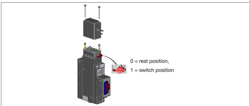
Operating Manual Override
Operate the manual override only when the electrical power supply is switched off. To actuate, depress the manual override button and rotate it 90° clockwise until it hits the mechanical stop. In this position, the override is locked in the operated state and will not reset automatically. To resume normal electrical operation, turn the override back 90° counter-clockwise to zero position.
The valve island supports multiple standard pneumatic circuit configurations:
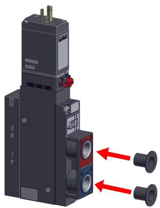
A 4/2-way valve station can be converted to specific 3/2-way operations by sealing one of the working outlet ports with an airtight stopper plug:
| Port 2 (B) | Port 4 (A) | Resulting Circuit Function |
|---|---|---|
| Closed with plug | Open | Function C (Normally Closed) |
| Open | Closed with plug | Function D (Normally Open) |
Valve island Type 8640 utilizes modular pneumatic base rails that interconnect laterally. Assembly begins from the left connection module, snapping intermediate base segments together using upper and lower latching hooks.
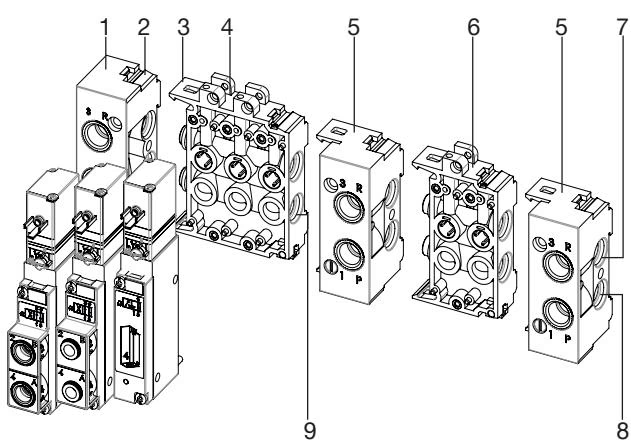
| Item | Designation |
|---|---|
| 1 | Left connection module |
| 2 | Latch tab |
| 3 | Latch hook |
| 4 | Base modules (3-fold) |
| 5 | Right connection module |
| 6 | Base modules (2-fold) |
| 7 | Exhaust channel 3 (R) |
| 8 | Supply channel 1 (P) |
| 9 | Inter-module O-rings |
Before sliding modular blocks together, ensure that two elastomer O-rings are seated between adjacent channel faces and lightly lubricate them with compatible grease. Engage the lower latch hook into the mating groove, pivot the module upwards, and lock the upper latch hook into engagement.

Sealing Integrity on Valve Bases
Each valve requires three O-rings inserted into the recesses on the rear body face prior to fastening. Crushed, pinched, or missing profile seals cause external leakage and internal pressure cross-talk. Fasten each valve body onto the base module using two screws tightened to a recommended torque of 0.6 Nm ± 0.1 Nm.
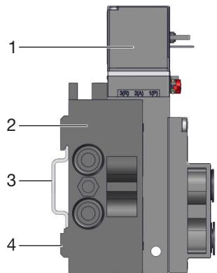
The complete block installs directly onto standard symmetrical DIN rails conforming to EN 50022 (dimensions 35 x 15 mm or 35 x 7.5 mm):
When connecting pneumatic piping into threaded ports, adhere to the following torque limits:
| Port Thread Size | Port Marking / Function | Recommended Torque [Nm] | Maximum Torque [Nm] |
|---|---|---|---|
| G 1/4 / NPT 1/4 | Supply 1 (P), Exhaust 3 (R/S) | 4 to 7 | 20 |
| G 1/8 / NPT 1/8 | Supply 1 (P), Exhaust 3 (R/S), Outlets 2 (B) / 4 (A) | 3 to 6 | 7 |
Article 20149423 provides bottom-facing D8 push-in connections on the pneumatic base. Reliable sealing and hose retention require strict compliance with dimensional and mechanical specifications.
Hose Line Requirements
To ensure proper hose retention under pressure, push-in fittings must meet the minimum tensile pull-out forces defined by DIN ISO 14743:2020:
| Hose Outer Diameter (OD) | Polyamide (PA) Minimum Tensile Force | Polyurethane (PU) Minimum Tensile Force |
|---|---|---|
| 3 mm (1/8 in / 3.17 mm) | 60 N | 25 N |
| 4 mm (5/32 in / 4.00 mm) | 70 N | 50 N |
| 6 mm (1/4 in / 6.35 mm) | 120 N | 100 N |
| 8 mm (5/16 in / 8.00 mm) | 170 N | 150 N |
| 10 mm (3/8 in / 9.52 mm) | 250 N | 200 N |
| 12 mm (1/2 in / 12.7 mm) | 300 N | 200 N |
| 14 mm | 300 N | 250 N |
| 16 mm (5/8 in / 16.0 mm) | 350 N | 300 N |
Tubing Retention with Softer Polymers
When using softer polyurethane (PU) tubing, internal support sleeves (Burkert ID 20099400) can be inserted into the tube core to eliminate wall collapse under clamping teeth and guarantee joint seal integrity.
Electrical signals are distributed to individual valve coils via the collective socket interface. All electronic components within the module are susceptible to electrostatic discharge (ESD).
Electrostatic Precautions
Observe ESD handling precautions compliant with EN 61340-5-1. Never touch internal terminal pins or circuit boards while electrical supply voltage is active.
Reliability During Continuous Operation
When operating in continuous duty applications with long static periods, perform at least 1 to 2 switching cycles per day during idle phases to maintain mechanical responsiveness and valve seal compliance.
| Fault Observed | Probable Cause | Corrective Action |
|---|---|---|
| Valves fail to switch | Missing or insufficient control voltage | Verify wiring connections; confirm supply voltage matches collective socket rating. |
| Manual override not in home position | Rotate manual override back counter-clockwise to zero position. | |
| Insufficient or absent pneumatic supply | Establish high-volume pressure feed; verify system operating pressure is ≥ 2.0 bar. | |
| Delayed switching or blow-off at exhaust ports | Air supply capacity insufficient | Ensure upstream regulator, filter, and shutoff valves provide adequate volume; maintain pressure ≥ 2.0 bar. |
| Valves energized prior to pneumatic pressurization | Apply pneumatic line pressure to the valve island before initiating electrical switching cycles. | |
| Excessive back-pressure on exhaust ducts | Inspect exhaust silencers for clogging; clean silencer elements or replace with larger volume silencers. | |
| Particulate contamination inside pilot or main stage | Apply brief pressure pulses through exhaust ducts to blow out foreign matter, or replace the affected valve. | |
| Leakage across valve block joints | Missing or pinched O-rings between base modules | Disassemble sub-blocks, inspect O-ring seals, and replace missing or crushed elastomer rings. |
| Misaligned or damaged flat seals beneath valve slice | Loosen mounting screws, realign flat profile seals, and retorque valve body screws to 0.6 Nm. |
Explore similar products in our catalog


