

PN16

BURKERT 320867 (Type 6407) is a 2/2-way servo-assisted piston solenoid valve featuring NPT 3/4 ports, brass body, stainless steel seat, PTFE/graphite seals, 0-10 bar operating pressure, and 230-240 V AC Kick and Drop coil.
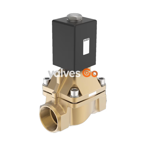
BURKERT 320867 (Type 6407) is a servo-assisted 2/2-way piston valve designed for controlling, shutting off, and dosing neutral gases, steam, and liquid media up to a kinematic viscosity of 21 mm²/s. Operating according to circuit function A (normally closed), the valve features a fixed mechanical coupling between the pilot plunger and the main piston system. This direct mechanical link enables reliable opening across the entire pressure span from 0 to 10 bar without requiring differential operating pressure.
Configured specifically for steam and high-temperature thermal duties, article 320867 combines an NPT 3/4 threaded brass body with an integrated stainless steel valve seat, PTFE seat sealing, and external graphite seals. The electromagnetic drive utilizes a 42 mm epoxy-encapsulated coil (Size K) equipped with Kick and Drop electronics. This double-coil system provides high inrush power (85 W for 500 ms) to pull the core, then drops to a low holding power (8.5 W cold / 7 W warm) to minimize thermal load and electrical consumption during steady-state energization.
| Specification Parameter | Technical Value |
|---|---|
| Article Number | 320867 |
| Valve Type | Type 6407 |
| Circuit Function | CF A (2/2-way, normally closed) |
| Orifice Size (DN) | 20 mm (3/4") |
| Port Connection | Internal thread NPT 3/4 |
| Operating Pressure Range | 0 to 10 bar |
| Flow Value Kv (Water) | 5.7 m³/h (5.6 m³/h per DIN EN 1902-1 rating) |
| Flow Value QNn (Gas) | 6,100 l/min |
| Nominal Voltage | 230 to 240 V AC (50/60 Hz) |
| Coil Type / Size | Kick and Drop coil / Size 42 mm (Size K) |
| Coil Insulation Class | Epoxy Class H |
| Body Material | Brass |
| Valve Seat Material | Stainless steel |
| Sealing Material | PTFE seat seal, graphite external sealing |
| Medium Temperature Range | -40 °C to +150 °C (0 °C to +150 °C for steam/water) |
| Maximum Ambient Temperature | +45 °C |
| Viscosity Limit | Max. 21 mm²/s (cSt) |
| Switching Time (DN 20) | Opening: 30 ms; Closing: 250 ms |
| Installation Length | 100 mm |
| Electrical Connection | Plug pattern Form A acc. to DIN EN 175301-803 |
| Protection Rating | IP65 (with properly fitted cable plug) |
| Approvals | cURus Recognized (UL 429), CE |
The magnetic circuit and fluid body are engineered for extended endurance in steam service. The stopper and armature guide tube are welded together to enhance pressure resistance and eliminate external leakage paths.
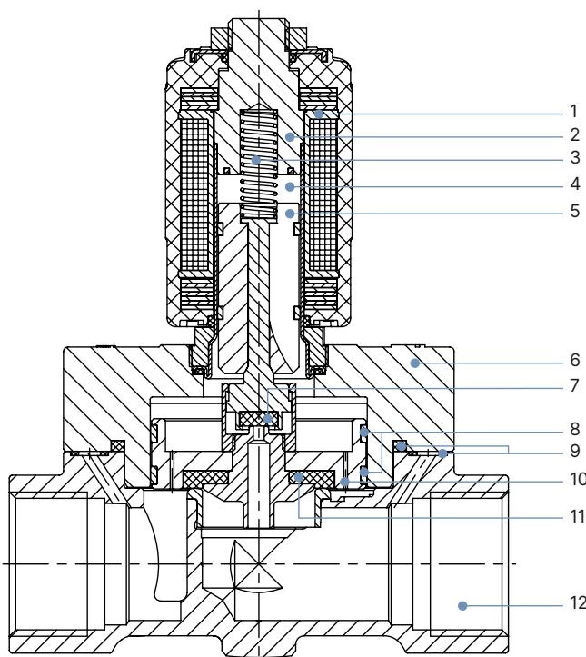
| Item No. | Element | Material Designation |
|---|---|---|
| 1 | Coil | Epoxy |
| 2 | Stopper | Stainless steel 1.4113 (AISI 434) |
| 3 | Spring | Stainless steel 1.4310 (AISI 301) |
| 4 | Armature guide tube | Stainless steel 1.4303 (AISI 305 / 308) |
| 5 | Core | Stainless steel 1.4113 (AISI 434) |
| 6 | Cover | Brass |
| 7 | Seal | PTFE |
| 8 | Piston ring | PTFE |
| 9 | Sealing ring | Graphite |
| 10 | Plunger | Brass |
| 11 | Piston seal | PTFE |
| 12 | Body | Brass (fitted with stainless steel seat) |
Article 320867 features an NPT 3/4 female threaded connection with an overall installation face-to-face length of 100 mm.
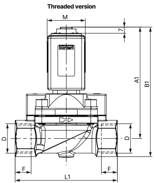
| DN | A1 [mm] | B1 [mm] | G Thread (D1 / F1) | NPT Thread (D2 / F2) | Rc Thread (D3 / F3) | E1 [mm] | L1 [mm] | SW [mm] |
|---|---|---|---|---|---|---|---|---|
| 13 | 118.7 | 132.7 | - | - | Rc 3/8 / 10.1 mm | 40 | 65 | 27 |
| 13 | 118.7 | 132.7 | G 1/2 / 14.0 mm | NPT 1/2 / 13.7 mm | Rc 1/2 / 13.2 mm | 40 | 65 | 27 |
| 20 (320867) | 119.7 | 135.7 | G 3/4 / 16.0 mm | NPT 3/4 / 14.0 mm | Rc 3/4 / 14.5 mm | 60 | 100 | 32 |
| 25 | 125.7 | 146.2 | G 1 / 18.0 mm | NPT 1 / 16.8 mm | Rc 1 / 16.8 mm | 70 | 115 | 41 |
| 32 | 142.7 | 167.7 | G 1 1/4 / 20.0 mm | NPT 1 1/4 / 17.3 mm | Rc 1 1/4 / 19.1 mm | 85 | 126 | 50 |
| 32 | 146.7 | 176.7 | G 1 1/2 / 22.0 mm | NPT 1 1/2 / 17.3 mm | Rc 1 1/2 / 19.1 mm | 85 | 126 | 60 |
| Coil Size | M [mm] | N [mm] | O [mm] |
|---|---|---|---|
| K (42 mm) | 42 | 27 | 55.5 |
| L (65 mm) | 65 | 37.5 | 72.0 |
The Kick and Drop coil incorporates double-coil technology with integrated control electronics. During switching, the electronics activate both coils in parallel for approximately 500 ms to provide the pulling force needed to overcome fluid forces and spring tension, then switch over to single-coil holding operation.
| Orifice DN [mm] | Coil Size [mm] | AC Inrush [VA] | AC Hold [VA] | AC Hold [W] | DC Cold [W] | DC Warm [W] | Kick & Drop Inrush (500 ms) [W] | Kick & Drop Hold Cold [W] | Kick & Drop Hold Warm [W] |
|---|---|---|---|---|---|---|---|---|---|
| 13 | 42 | 140 | 41 | 16 | 21 | 16 | 85 | 8.5 | 7 |
| 20 (320867) | 42 | 150 | 41 | 16 | - | - | 85 | 8.5 | 7 |
| 25 | 42 | 160 | 41 | 16 | - | - | 85 | 8.5 | 7 |
| 32 | 42 | 170 | 41 | 16 | - | - | 85 | 8.5 | 7 |
| 20...32 | 65 | - | - | - | 28 | 21 | - | - | - |
Duty Cycle Limits for Kick and Drop Technology
Valves fitted with Kick and Drop electronics are restricted to a maximum duty cycle of 50% and a maximum switching frequency of six operations per minute. Continuous cycling above this threshold causes internal thermal overload.
Functional Reliability During Extended Standstill
When valves remain de-energized or unactuated for prolonged production pauses, cycle the valve electrically once or twice per day to maintain movement integrity and prevent pilot sticking.
Prior to mounting, flush all supply piping to remove particulate debris, weld beads, and pipe scale. Observe the cast arrow on the valve body indicating fluid flow direction.
Upstream Filtration Requirement
Install an upstream particulate strainer with a mesh rating of ≤ 500 µm directly ahead of the valve inlet. Foreign matter entering the internal pilot passages can impair shut-off sealing.
Mount the valve in any spatial orientation, though an upright actuator position with the coil facing upward is preferred to minimize internal particulate settlement inside the armature tube. Use an open-end wrench on the designated body flats (SW 32 mm) when threading into the pipeline. Never use the solenoid coil as a lever.
Electrical Shock and Grounding Requirement
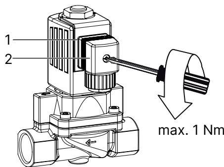
Always connect the protective earth conductor (PE) to the terminal plug and verify electrical continuity between the solenoid coil housing and the valve body. Tighten the cable plug center fixing screw to a torque of max. 1 Nm. Verify that the sealing gasket between the plug and the coil socket is seated properly to preserve IP65 ingress protection.
Depressurize pipelines, drain the working fluid, and disconnect electrical power before performing any servicing, disassembly, or coil replacement.
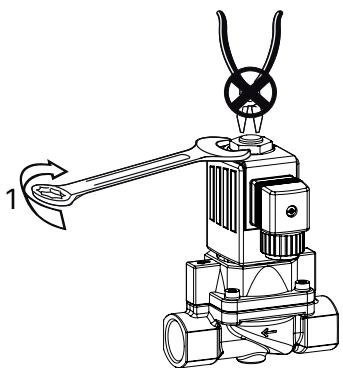
Solenoid Energization Precaution
Never apply electrical voltage to the solenoid coil while it is removed from the armature guide tube. Operating the coil without its magnetic core and valve body will cause severe overheating and permanent coil destruction within seconds.
When securing the coil, tighten the top fixing nut using an open-end wrench to the specified torque. Do not continue turning the nut once firmly seated.
| Valve Type | DN [mm] | Coil Nut Torque [Nm] | Valve Cover Screws [Nm] | Stopper with Tube [Nm] | | :--- | :--- | :--- | :--- | :--- | | | 6407 | 13 | 15 | 3.0 to 4.0 | 49.0 to 51.0 | | 6407 (320867) | 20 | 15 | 6.0 to 7.0 | 49.0 to 51.0 | | 6407 | 25 | 15 | 8.0 to 10.0 | 49.0 to 51.0 | | 6407 | 32 | 15 | 8.0 to 10.0 | 49.0 to 51.0 | | 6407 | 50 | 19 | 13.0 to 17.0 | 110.0 to 115.0 |
Factory replacement wear parts are available in structured sets. When placing replacement orders, state both the required item position and the complete article number (320867).
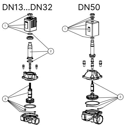
| Item No. | Spare Part Description |
|---|---|
| 1 | Coil set (complete encapsulated solenoid assembly) |
| 3 | Armature wearing part set (plunger, spring, seals, and guide subassembly) |
Explore similar products in our catalog


