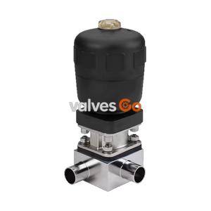
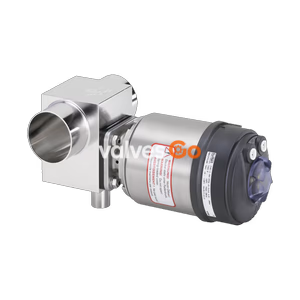
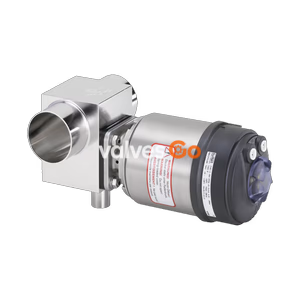
Type 2032

BURKERT 323642 Type 2032 pneumatic diaphragm T-valve. Features a stainless steel body, PTFE/EPDM diaphragm, weld end connection, and normally closed (NC) control function.
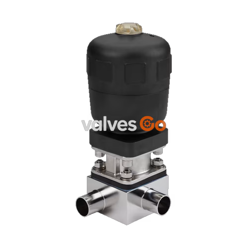
BURKERT 323642 Type 2032 externally controlled diaphragm T-valve consists of a pneumatically operated piston actuator, a PTFE/EPDM diaphragm, and a stainless steel T-valve body. The proven and robust actuator with a plastic housing ensures use in hygienic or aggressive ambient conditions. The flow-efficient valve bodies with little dead space enable high flow rates and a wide range of possible uses. The actuator has a compact, autoclavable design (PPS variant).
This specific model features a 3/4 inch (DN 20) weld end connection conforming to ASME BPE / DIN 11866 Series C, a PTFE diaphragm with an EPDM backing membrane, and operates with a normally closed (NC) control function A.
| Product properties | |
|---|---|
| Block body material | Stainless steel block material 1.4435 according to DIN EN 10088 and 316L according to ASME BPE |
| Diaphragm material | PTFE with EPDM backing membrane |
| Actuator material | PPS (Polyphenylene sulphide) |
| Standard surface quality | Internally electrically polished: Ra ≤ 0.38 μm (ASME BPE SF4 / DIN HE4) (externally Ra ≤ 1.6 μm) |
| Maximum pilot pressure | 7 bar (for actuator size 40 to 125 / PPS) |
| Pilot air port | Thread G 1/8 for actuator size 40 and 50 |
| Operating medium | Neutral gases and liquids, highly purified, sterile, aggressive or abrasive mediums |
| Medium temperature | -10 °C to +130 °C (steam sterilisation max. +140 °C for 60 min) |
| Control medium | Neutral gases, air |
| Ambient temperature (PPS) | +5 °C to +140 °C (actuator size ≤ 80 mm) |
| Symbol | Description |
|---|---|
| Control function A (CF A) | Pneumatically operated T-valve. Normally closed by spring force. |
| Control function B (CF B) | Pneumatically operated T-valve. Normally opened by spring force. |
| Control function I (CF I) | Pneumatically operated T-valve on either side. Switching position dependent on external control. |
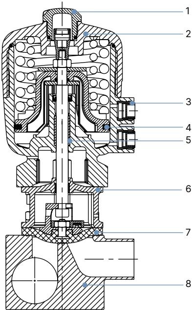
| No. | Element | Material |
|---|---|---|
| 1 | Transparent cap | Polysulfone PSU |
| 2 | Cover | Polyphenylene sulphide PPS (standard) / Polyamide PA (on request) |
| 3 | Pilot air ports | Stainless steel 1.4305 |
| 4 | Piston seal | FKM |
| 5 | Socket | Sinter metal |
| 6 | Interface | Stainless steel 1.4404 |
| 7 | Diaphragm | PTFE/EPDM (EA) |
| 8 | Valve body | Stainless steel |
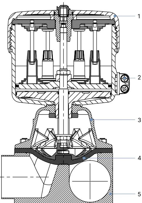
| No. | Element | Material |
|---|---|---|
| 1 | Cover | Polyamide PA |
| 2 | Pilot air ports | Stainless steel 1.4305 |
| 3 | Diaphragm bonnet | Stainless steel 1.4308 |
| 4 | Diaphragm | PTFE/EPDM (EA) |
| 5 | Valve body | Stainless steel |
INFO
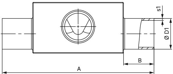
Dimensions in mm, unless otherwise stated.
Diaphragm size 8…50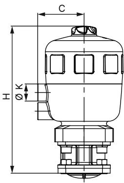
Diaphragm size 65…100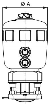
| Diaphragm size | Actuator size ∅ | ∅ A | C | K | H |
|---|---|---|---|---|---|
| 8 | 40 (C) | 53 | 34 | G 1/8" | 111 |
| 15 | 50 (D) | 64 | 39 | G 1/8" | 137 |
| 15 | 63 (E) | 80 | 52 | G 1/4" | 154 |
| 20 | 63 (E) | 80 | 52 | G 1/4" | 165 |
| 20 | 80 (F) | 101 | 52 | G 1/4" | 186 |
| 25 | 63 (E) | 80 | 52 | G 1/4" | 170 |
| 25 | 80 (F) | 101 | 60 | G 1/4" | 190 |
| 40 | 100 (G) | 127 | 73 | G 1/4" | 246 |
| 40 | 125 (H) | 158 | 86 | G 1/4" | 284 |
| 50 | 100 (G) | 127 | 73 | G 1/4" | 254 |
| 50 | 125 (H) | 158 | 86 | G 1/4" | 288 |
| 65 | 175 (K) | 211 | 130 | G 1/4" | 350 |
| 80 | 175 (K) | 211 | 130 | G 1/4" | 350 |
| 80 | 225 (L) | 261 | 155 | G 1/4" | 345 |
| 100 | 225 (L) | 261 | 155 | G 1/4" | 345 |
INFO
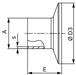
The clamp dimensions must be added to the welded connection dimensions.
WARNING
Pressure data [bar]: Overpressure to atmospheric pressure. Static: When closed, the valve is pressurised on one side with the maximum operating pressure.
| Diaphragm size | Actuator size ∅ | Pilot pressure [bar] | Maximum static operating pressure for PTFE/EPDM [bar] |
|---|---|---|---|
| 8 | 40 (C) | 5.0...7 | 10 |
| 15 | 63 (E) | 5.0...7 | 10 |
| 20 | 63 (E) | 5.5...7 | 10 |
| 20 | 80 (F) | 5.0...7 | 10 |
| 25 | 80 (F) | 5.5...7 | 10 |
| 40 | 100 (G) | 5.5...7 | 9 |
| 40 | 125 (H) | 5.5...7 | 10 |
| 50 | 125 (H) | 5.5...7 | 10 |
| 65 | 175 (K) | 5.0...6 | 6 |
| 80 | 225 (L) | 5.0...6 | 10 |
| 100 | 225 (L) | 5.0...6 | 7 |
Any installation position is possible, preferably with the actuator facing up. For leakage detection, one of the relief bores in the diaphragm bonnet must be at the lowest position.
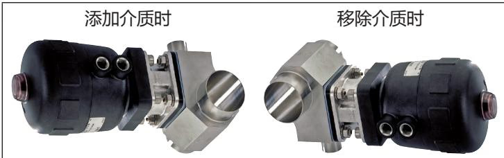
The following installation positions are recommended for the installation of T-valve bodies in circular pipelines:
TIP
Ensure automatic draining is maintained by observing the pipeline inclination angle (1° … 5°) and the self-draining angle of the valve body.
Explore similar products in our catalog