

PN16

BURKERT 328661 is a 16-bank Type 8652 AirLINE Quick modular valve island featuring PROFIBUS DPV1 fieldbus communication, 5/2-way monostable valves, brass D10/D6 ports, and an operating pressure range of -1 to 10 bar.
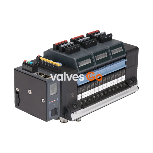
BURKERT 328661 is a 16-bank Type 8652 AirLINE modular valve island configured for pneumatic process automation. The assembly integrates 16 valve slots fitted with 5/2-way monostable CF-H pneumatic directional valves, communicating through a PROFIBUS DPV1 fieldbus module equipped with a 9-pin Sub-D interface. Constructed with an aluminum AirLINE Quick interface and brass push-in fittings (D10 supply connection and D6 working ports), the unit operates at nominal pressures from -1 bar to 10 bar, pilot pressure from 3 bar to 10 bar, and medium/ambient temperatures from -10 °C to +55 °C.
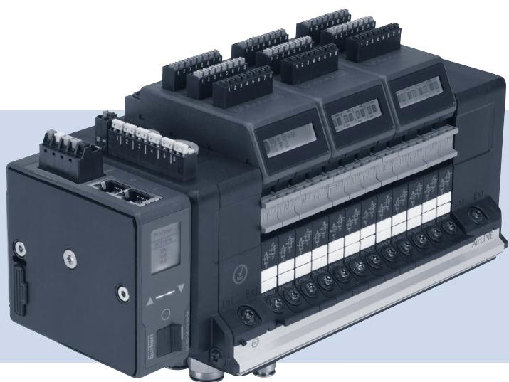
Article 328661 is equipped with 16 identical pneumatic valve stations. Each valve position utilizes a 5/2-way monostable spool valve (circuit function CF-H) driven by Type 6164 pilot solenoid valves acting on Type 6534 pneumatic bodies. Main air delivery and working ports are arranged through high-density brass push-in connections directly mounted to an aluminum AirLINE Quick base.
| Parameter | Source Specification |
|---|---|
| Number of Valve Slots | 16 PCE |
| Valve Positions 1 to 16 | 5/2-way monostable CF-H |
| Pilot Valve Element | Type 6164 (pilot control for Type 6534 pneumatic valve) |
| Supply Port Size / Material | D10 push-in / Brass |
| Working Port Size / Material | D6 push-in / Brass |
| AirLINE Quick Adapter Material | Aluminium |
| Pilot Air Configuration | Internal auxiliary pilot air |
| Intermediate Feed Quantity | 1 PCE |
| Additional Supplies (Left / Right / Middle) | Without |
| Check Valves in Exhaust Ports 3 (R) and 5 (S) | No |
| Pneumatic HotSwap in Port 1 (P) | No |
The fieldbus interface links the 16 pneumatic stations directly to process control systems via PROFIBUS DPV1. Power delivery and communication run through isolated terminals designed for control cabinet integration.
| Characteristic | Technical Value |
|---|---|
| Modular Variant | Fieldbus module |
| Communication Protocol | PROFIBUS DPV1 |
| Hardware Interface 1 | Sub-D 9-pin |
| Digital Input Count | 0 DI (Electrical modules 1 to 4 without DI) |
| Nominal Operating Voltage | 24 V DC (±10%) |
| Current Consumption | 3 A |
| Max. Number of Valve Slice Functions Supported | 48 functions (16 used on article 328661) |
| Base Enclosure Protection Rating | IP20 (with suitable mating connectors) |
BURKERT 328661 conforms to explosion protection standards for equipment Group II, Category 3G (gas) and Category 3D (dust) when installed inside an approved enclosure.
| Operating Condition | Specification Limit |
|---|---|
| Nominal Working Pressure Range | -1.0 bar to 10.0 bar |
| Pilot Pressure Range | 3.0 bar to 10.0 bar |
| Medium Temperature Range | -10 °C to +55 °C |
| Ambient Operating Temperature Range | -10 °C to +55 °C |
| Enclosure Internal Temperature Limit | ≤ +55 °C (maintains Temperature Class T4 compliance) |
| AirLINE Quick External Surface Temperature | ≤ 80 °C (when cabinet ambient is ≤ +55 °C) |
| ATEX Gas Protection Rating | II 3G Ex ec IIC Gc |
| ATEX Dust Protection Rating | II 3D Ex tc IIIC Dc |
| ATEX Certificate | BVS 20 ATEX E 031 U |
| IECEx Certificate | IECEx BVS 20.0024 U |
| CCC Certification | GB/T 3836.2021 series standards (via SITIIAS) |
| Production Audit Authority | PTB (CE0102) |
Installation Requirements and Safety Guidelines
For safe operation in Zone 2 / Zone 22 hazardous locations, the following operating criteria must be observed:
Every Type 8652 valve island intended for potentially explosive environments features two label sets: a standard manufacturer plate and an Ex approval plate.
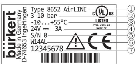
| Position | Description | Value / Specification |
|---|---|---|
| 1 | Device Type | Type 8652 AirLINE |
| 2 | Pressure Range | 3–10 bar (pilot) / -1–10 bar (nominal) |
| 3 | Ambient Temperature Range | -10 °C to +55 °C |
| 4 | Nominal Voltage & Current | 24 V DC / 3 A |
| 5 | Serial Number | Factory encoded |
| 6 | Manufacturing Code | Factory encoded |
| 7 | Order Number (Ident-No.) | 328661 |
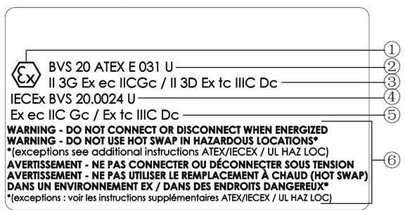
| Position | Description (Code PX68) | Description (Code PU17) |
|---|---|---|
| 1 | Ex Marking Symbol | US/CA Zone Marking (Gas): Cl I, ZN 2, AEx ec IIC Gc / Ex ec IIC Gc U |
| 2 | ATEX Certificate: BVS 20 ATEX E 031 U | US/CA Zone Marking (Dust): Cl II, ZN 22, AEx tc IIIC Dc / Ex tc IIIC Dc U |
| 3 | ATEX Gas/Dust: II 3G Ex ec IIC Gc / II 3D Ex tc IIIC Dc | US/CA Division Marking: Cl I, Div 2, Gr A, B, C, D / Cl II, III, Div 2, Gr F, G |
| 4 | IECEx Certificate: IECEx BVS 20.0024 U | ATEX Certificate: BVS 20 ATEX E 031 U |
| 5 | IECEx Gas/Dust: Ex ec IIC Gc / Ex tc IIIC Dc | Ex Marking Symbol |
| 6 | Safety Warning: Electrical Connection & HotSwap | ATEX Gas/Dust: II 3G Ex ec IIC Gc / II 3D Ex tc IIIC Dc |
| 7 | — | IECEx Certificate: IECEx BVS 20.0024 U |
| 8 | — | IECEx Gas/Dust: Ex ec IIC Gc / Ex tc IIIC Dc |
| 9 | — | Safety Warning: Electrical Connection & HotSwap |
Explore similar products in our catalog


