Skip to content
Normally Open (NO)Weld EndDN 50Stainless SteelEPDM DiaphragmPPS Actuator

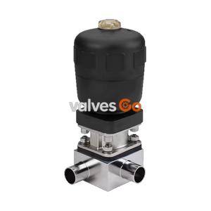
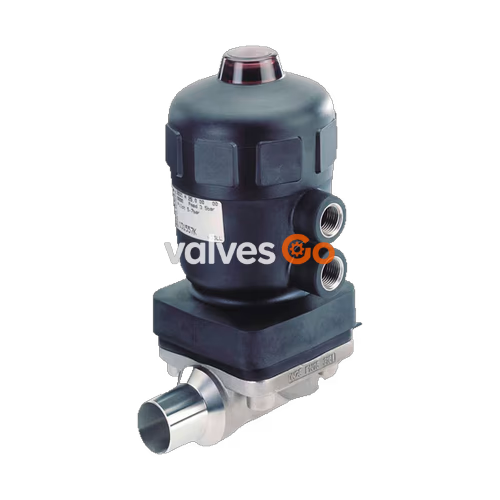
BURKERT 348435 Type 2031 2/2-Way Diaphragm Valve, Weld End, DN50

Bürkert 348435 Type 2031 2/2-way piston-operated diaphragm valve. Features normally open (CF B) operation, stainless steel body, weld end DN50, EPDM diaphragm, and PPS actuator.
BURKERT 348435 Type 2031 2/2-Way Diaphragm Valve, Weld End, DN50

Bürkert 348435 Type 2031 is an externally controlled 2/2-way piston-operated diaphragm valve designed for reliable operation in hygienic or aggressive environments. This specific configuration features Control Function B (normally open by spring force), a stainless steel valve body with DN 50 (2 inch) weld end connections, an EPDM high-temperature diaphragm, and a compact, autoclavable PPS (Polyphenylene sulphide) actuator. The flow-optimised valve body with minimal dead space enables high volume flow rates (Kv value 47 m³/h) and ensures excellent cleanability.

The valve uses neutral gases or air to control the flow of media and is self-draining when installed in the appropriate position. It is suitable for neutral gases and liquids, as well as highly purified, sterile, aggressive, or abrasive media.

Product Identification

The type label provides essential technical specifications and identification data for the valve.
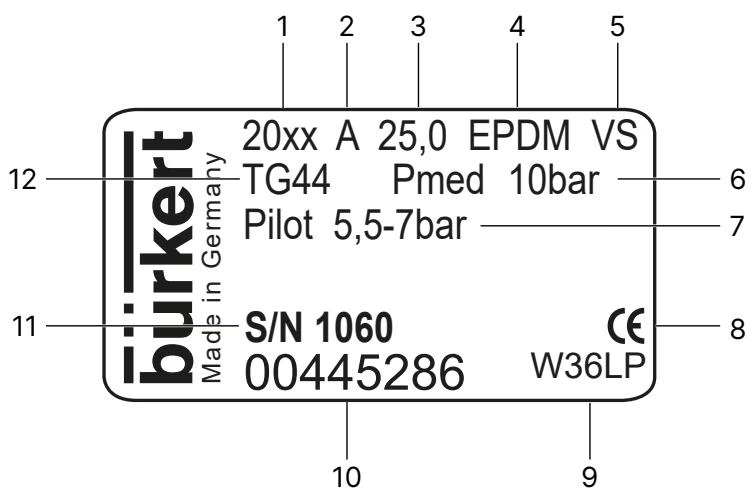
Bürkert 348435 Type 2031 type label description

Fig: Description of the type label (example)

Technical Data

Operating Conditions

Permissible Temperatures:

  • Ambient temperature (PPS actuator): +5 °C to +90 °C (short-term up to +140 °C for actuator sizes 100/125).
  • Medium temperature (Stainless steel body): -10 °C to +140 °C (short-term up to 150 °C).
  • Medium temperature (EPDM diaphragm): -10 °C to +143 °C (Steam sterilisation max. +150 °C for 60 min).

Operating Pressure:

  • Maximum permissible operating pressure: 10 bar.

Risk of bursting due to overpressure

If the device bursts, escaping media may cause injuries, burns or scalds. Do not exceed the maximum permissible pilot pressure or maximum permissible operating pressure. Observe the permissible ambient temperature and medium temperature.
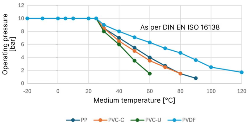
BURKERT 348435 Bürkert 348435 Type 2031 pressure-temperature diagram

Pilot Pressure:

  • Permissible pilot pressure (PPS actuator): 2 to 7 bar.
  • Pilot air port size: G 1/4.

Malfunction due to incorrect pilot pressure

Valves with reduced spring force require reduced pilot pressure. Do not select a pilot pressure that is higher than required, as this is important for the service life of the diaphragm.

Installation

Ensuring Self-Draining

The installer and the operator are responsible for ensuring self-draining. The following points must be observed for optimum self-draining:
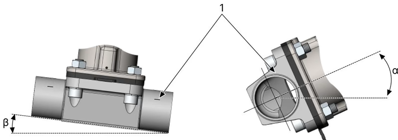
  1. Inclination angle of the pipeline: The inclination angle is determined by the installer or operator. For pipelines, the inclination angles specified in the valid ASME BPE standard are recommended.
  2. Self-draining angle for valve body: The marking for self-draining angles on the port connection serves as a guide and must point upwards. The actual angle must be set with a suitable measuring tool.

Bürkert 348435 Type 2031 installation position for self-draining

Fig: Installation position for self-draining

Welding the Valve Body into the Pipeline

Damage to the diaphragm or the actuator

The diaphragm and actuator can be damaged when welding or bonding the valve body into the pipeline. Remove the actuator and diaphragm from the valve body before installation.

  1. Remove the actuator from the valve body.
  2. Weld the valve body into the pipeline.
  3. After welding the surface of the valve body, smooth by sanding if necessary and clean the valve body carefully.
  4. Install the actuator on the valve body.

Compressor Alignment

Risk of crushing

If the compressor is not positioned correctly and the actuator is actuated, this may result in injuries and damage to the device. Before actuating the actuator, ensure that the compressor is in the correct position.
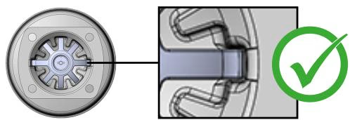
Bürkert 348435 Type 2031 correct and incorrect position of the compressor
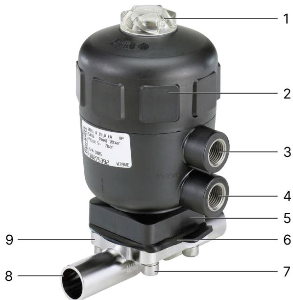
Fig: Correct and incorrect position of the compressor

Maintenance and Repair

Inspection Intervals

  • After the first steam sterilisation and when required: Tighten the body screws crosswise.
  • After 10^5 switching cycles at the latest: Check the diaphragm for wear. Shortened inspection intervals are required for muddy and abrasive media.

Replacing the Diaphragm (Control Function B)

  1. Clamp the valve body in a holding device (only for devices which have not yet been installed).
  2. Loosen the body screws crosswise and remove the actuator and diaphragm from the valve body.
  3. Unbutton or unscrew the old diaphragm.
  4. Attach the new diaphragm to the compressor according to the fastening type. The identification tab must be perpendicular to the flow direction.
  5. Place the actuator together with the diaphragm on the valve body.
  6. Slightly tighten the body screws crosswise without applying pressure until the diaphragm rests between the valve body and actuator. Do not fully tighten the screws yet.
  7. Actuate the valve twice to position the diaphragm correctly.
  8. Pressurise the upper pilot air port with compressed air: valve closes.
  9. With pressure, tighten the body screws in three stages (approx. 1/3, then 2/3 and then full tightening torque), in each case crosswise. For DN 50 EPDM diaphragms, the full tightening torque is 12 Nm (tolerance: +10%).

BURKERT 348435 Bürkert 348435 Type 2031 product overview and components