

PN16

BURKERT 349748 (Type 6281) is an ATEX/IECEx-certified servo-assisted 2/2-way NC solenoid valve featuring a stainless steel body, G 1 1/4 ports, DN25 orifice, FKM seals, and 24 V AC/DC terminal box.
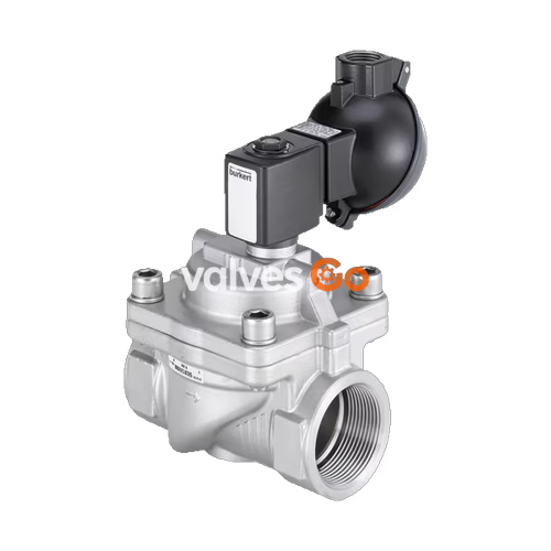
BURKERT 349748 (Type 6281) is a servo-assisted 2/2-way diaphragm valve with an explosion-proof terminal box connection, designed for shut-off, dosing, and control of neutral fluids and gases. Built with a cast stainless steel 1.4408 (CF8M) valve body and FKM (fluororubber) seals, this valve configuration operates across a pressure span of 0.2 bar to 16 bar. The primary connection is an internal thread G 1 1/4 with an orifice size of DN 25 mm, delivering a water flow coefficient (Kv) of 12 m³/h and a gas flow rate (QNn) of 13,000 l/min.
The valve utilizes a damped diaphragm assembly to achieve quiet closing under process pressures. Actuation is driven by a centrally screwed, vibration-resistant solenoid actuator rated for 24 V AC/DC (50/60 Hz). With certified explosion protection according to ATEX and IECEx standards (Ex eb mb IIC T4 Gb and Ex mb tb IIIC T130 °C Db), article 349748 fulfills European and international safety requirements for potentially explosive gas and dust environments.
Differential Pressure Requirement
Type 6281 is a servo-assisted valve and requires a permanent minimum differential pressure of 0.2 bar between the inlet and outlet to actuate reliably. A differential pressure of 0.5 bar is required to fully open the valve cross-section.
| Specification Parameter | Technical Value |
|---|---|
| Circuit function | A (2/2-way valve, servo-assisted, normally closed) |
| Nominal diameter (DN) | 25 mm (1") |
| Pilot orifice | 1.4 mm |
| Port connection | G 1 1/4 internal thread |
| Installation length | 95 mm |
| Flow coefficient Kv (water, +20 °C) | 12 m³/h |
| Flow rate QNn (gas) | 13,000 l/min |
| Operating pressure range | 0.2 bar to 16 bar (gauge pressure) |
| Nominal pressure | PN 16 (DIN EN 1333) |
| Fluid media | Neutral liquids and gases compatible with housing and seal materials |
| Fluid viscosity | Maximum 21 mm²/s |
| Medium temperature (ATEX) | 0 °C to +90 °C (maximum medium temp must not exceed T4 limit minus 5 K) |
| Ambient operating temperature | -30 °C to +55 °C |
| Storage temperature | -40 °C to +80 °C |
| Operating voltage | 24 V AC/DC (50/60 Hz) |
| Voltage tolerance | ±10% |
| Duty cycle | 100% continuous operation (ED) |
| Degree of protection | IP65 according to DIN EN 60529 / IEC 60529 (with terminal box mounted) |
| Valve weight | 1.7 kg |
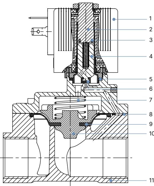
| Item | Component | Material |
|---|---|---|
| 1 | Coil body | Epoxy (H class insulation, rated for FKM execution) |
| 2 | Stopper | Stainless steel 1.4113 |
| 3 | Shading ring | Silver (Ag, fitted in stainless steel valve variants) |
| 4 | Magnetic core | Stainless steel 1.4113 |
| 5 | O-ring | FKM (fluororubber) |
| 6 | Core seal | FKM (fluororubber) |
| 7 | Core spring | Stainless steel 1.4310 |
| 8 | O-ring | FKM (fluororubber) |
| 9 | Diaphragm | FKM (fluororubber) |
| 10 | Diaphragm holder | PPS GF40 |
| 11 | Valve body | Stainless steel 1.4408 (CF8M) |
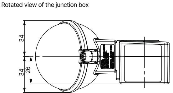
All dimensions are provided in millimeters (mm). For article 349748 (DN 25, G 1 1/4 connection, terminal box variant, coil size 6 / 40 mm):
| Dimension Code | Description | Value (mm) |
|---|---|---|
| A | Total valve height to actuator top | 111.6 |
| B | Total valve height to cable gland center | 136.6 |
| C | Solenoid body length | 70 |
| D | Solenoid depth including terminal cover | 85 |
| E | Centerline to port face distance | 46 |
| F1 | Thread engagement depth (G 1 1/4) | 20 |
| G1 | Thread connection | G 1 1/4 |
| L | Face-to-face body installation length | 95 |
| SW | Body hex width across flats | 50 |
| N | Clearance below valve body centerline | 15 |
| H | Solenoid width (coil size 6) | 40 |
| J | Centerline to side edge | 23.5 |
| K | Coil body height | 52 |
| P | Terminal box clearance offset | 74.8 |
| R | Actuator reach dimension | 103 |
| S | Total clearance height for disassembly | 177.7 |
Type 6281 solenoid actuators with explosion-proof terminal boxes utilize molded epoxy coils. Power consumption ratings for the ATEX/IECEx AC/DC execution on DN 13 to DN 50 valves (coil width 40 mm) are standardized:
| Execution Type | Orifice (DN) | Coil Size | Nominal Power (AC/DC) |
|---|---|---|---|
| ATEX/IECEx Terminal Box | 13 mm to 50 mm | 40 mm | 9 W |
Electrical and Thermal Safeguards
Do not energize the solenoid coil unless it is fully mounted and secured on the core guide tube of the valve body. Connecting the solenoid without a pre-installed valve causes rapid overheating and permanently damages the coil encapsulation. For continuous operation on AC supplies, monitor the core movement; a seized plunger will cause the coil to overheat.
Article 349748 is specifically certified for use in hazardous areas. The terminal box execution eliminates external plug connectors in favor of an integrated Ex e connection compartment:
| Certification Body | Approval Certificate | Identification Marking |
|---|---|---|
| ATEX | EPS 18 ATEX 1232 X | II 2 G Ex eb mb IIC T4 Gb II 2 D Ex mb tb IIIC T130 °C Db |
| IECEx | IECEx EPS 18.0110 X | Ex eb mb IIC T4 Gb Ex mb tb IIIC T130 °C Db |
| General Conformity | CE, EAC | Directives compliance verified via EU Declaration of Conformity |
Temperature Class Limitations
Under explosion protection standards, the process medium temperature must never exceed the permitted temperature class (T4: +135 °C) minus 5 K. For article 349748, the continuous medium temperature is rated from 0 °C to +90 °C in ATEX service.
Pressure and Voltage Hazard
Before loosening any process piping or servicing the valve, completely isolate system pressure and vent all connected process lines. Switch off all electrical power to the terminal box and secure against accidental re-energization.
| Article No. | Circuit Function | Port Connection | DN (mm) | Kv (m³/h) | Pressure (bar) | Body Material | Seal Material | Voltage / Frequency |
|---|---|---|---|---|---|---|---|---|
| 349748 | A (NC) | G 1 1/4 | 25 | 12 | 0.2–16 | Stainless steel | FKM | 24 V AC/DC |
| 349749 | A (NC) | G 1 1/4 | 25 | 12 | 0.2–16 | Stainless steel | FKM | 230 V AC/DC |
| Accessory Description | Ex Approval / Standards | Clamping Range | Article No. |
|---|---|---|---|
| Ex cable gland, polyamide (included standard) | PTB 13 ATEX 1015 X / IECEx PTB 13.0034X; II 2 G Ex e IIC Gb, II 2 D Ex tb IIIC Db IP68 | 7 mm to 13 mm | 773277 |
| Ex cable gland, nickel-plated brass (optional) | PTB 04 ATEX 1112 X / IECEx PTB 13.0027X; II 2 G Ex e IIC Gb, II 2 D Ex tb IIIC Db IP68 | 6 mm to 13 mm | 773278 |
| SC02-AC10 service set (special SW19 5 Nm tool and manual for turning terminal box) | — | — | 293488 |
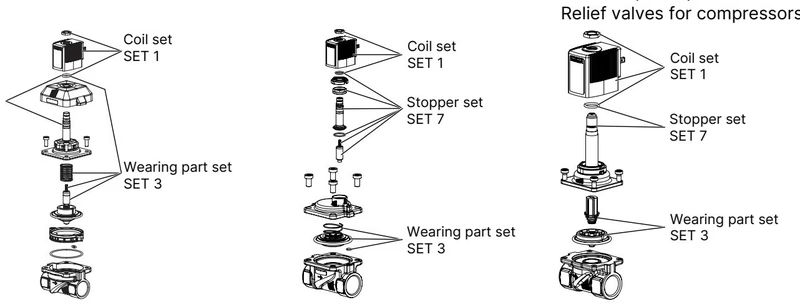
Original replacement parts are available in structured sets from Bürkert. Order spare part sets SET 1, SET 3, or SET 7 by quoting the device article number 349748.
Explore similar products in our catalog


