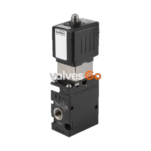
PN16

Burkert Type 8640 modular valve island (SKU 368485) for pneumatics. Features a 33mm 8-bank setup, G 1/2 pressure port, 2-8 bar operating pressure, and IP20 protection.
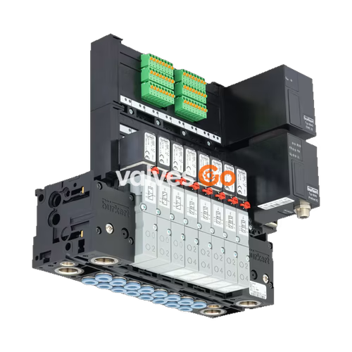
Burkert Type 8640 modular valve island (SKU 368485) is designed to solve diverse and complex control problems due to its systematic modular construction and combination of pneumatic and electrical interfaces. By putting together a row of pneumatic modules with different numbers of valves, 2 to 24 valve functionalities may be realized on one valve unit. Electrical connectivity is achieved by either fieldbus interfaces, common connection (parallel connection technique), or multipin interfaces.

The bodies and connection modules are made of high-quality plastic (polyamide) and are easy to assemble by means of the built-in snap connectors. The system allows different applications to be covered efficiently.
| Feature | Specification |
|---|---|
| Number of valve slots | Max. 24 (Max. 12 for impulse and double valves with multipol/fieldbus) |
| Maximum valve functions | Max. 48 (individual wiring), Max. 24 (multipol/fieldbus) |
| Pressure range | Vacuum to 10 bar (depending on valve type) |
| Operating medium | Oil-free or lubricated compressed dry air, neutral gases (5 μm filter recommended) |
| Compressed air quality | ISO 8573-1: 2010, Class 7.4.4 |
| Operating voltage | 24 V DC (±10% tolerance) |
| Degree of protection | IP20 / IP65 in closed control cabinets |
| Ambient temperature | 0 °C to + 55 °C (varies slightly by valve type) |
AirLINE Quick considerably reduces the use of components in the control cabinet. With the AirLINE Quick Adapter, the valve terminal is adapted directly to the control cabinet floor or control cabinet wall.
Advantages
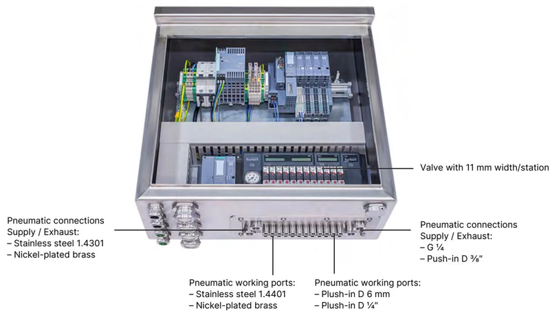
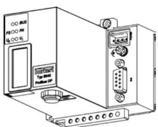
The Type 8640 system supports various electrical connection modules:
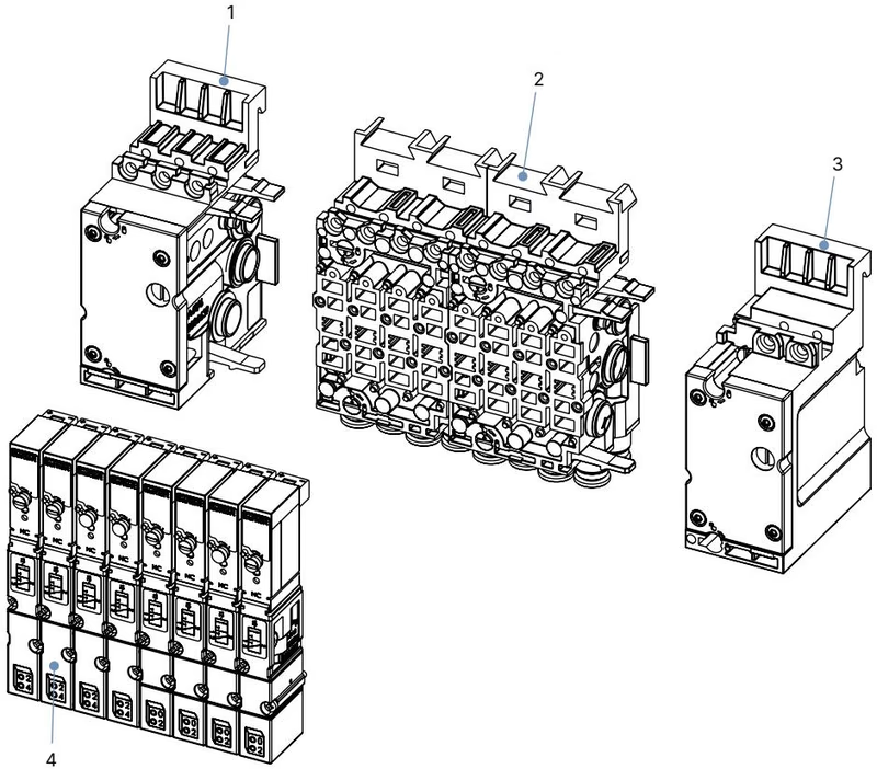
The pneumatic modules are assembled using connection modules and basic pneumatic modules.
DANGER
Risk of injury due to high pressure and escaping medium. Switch off the pressure before working on the device or system. Vent or drain the pipes. Risk of injury due to electric shock. Switch off voltage before working on the device or system. Secure against reactivation.
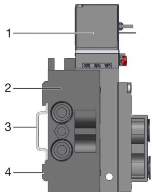
Standard rail installation:
Wall installation: Fasten the valve block directly to the wall with M4 screws.
Explore similar products in our catalog