PN16

Burkert 61481 (Type 0290) servo-assisted 2/2-way solenoid valve. Features a brass body, G 1 thread, FKM seal, 230V 50Hz, and operates from 0-16 bar without differential pressure.
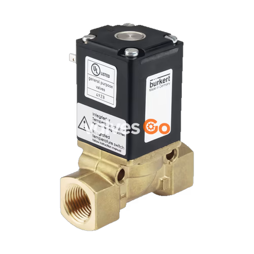
Burkert 61481 (Type 0290) is a servo-assisted 2/2-way diaphragm solenoid valve. The valve opens without differential pressure. The opening process is facilitated by the fix-coupling of the diaphragm to the magnetic core. The integrated 'soft-kick' function ensures gentle opening. The solenoid coils are moulded with an epoxy that has a high level of chemical resistance. Kick and drop electronics are moulded into all DC solenoid variants for reduced electrical power consumption.
| Symbol | Description |
|---|---|
| A (NC) | Circuit function A (CF A) 2/2-way solenoid valve Servo-controlled Normally closed |
| Product Properties | Details |
|---|---|
| Seal Material | FKM (NBR and EPDM available for other variants) |
| Body Material | Brass (Stainless steel 1.4581 available for other variants) |
| Coil Material | Epoxy |
| Valve Inner Parts | Brass, stainless steel |
| Orifice (Standard Variant) | DN 12...DN 50 (Model 61481 is DN 25) |
| Thermal Insulation Class | Epoxy coil class H |
| Duty Cycle | 100% continuous operation (unless otherwise specified) |
| Switching Time (DN 12...DN 25) | Opening: 100...250 ms Closing: 700...2000 ms |
| Voltage Tolerance | ±10% |
| Degree of Protection | IP65 with cable plug |
| Installation Position | As required, preferably with actuator upright |
| Seal Material | Permitted Media | Medium Temperature |
|---|---|---|
| NBR | Neutral gases and liquids (e.g. compressed air, water, hydraulic oil) | -10 °C...+80 °C |
| FKM | Per solutions, hot oils with additives | 0 °C...+120 °C |
| EPDM | Oil-free and fat-free media (e.g. hot water) | -30 °C...+100 °C |
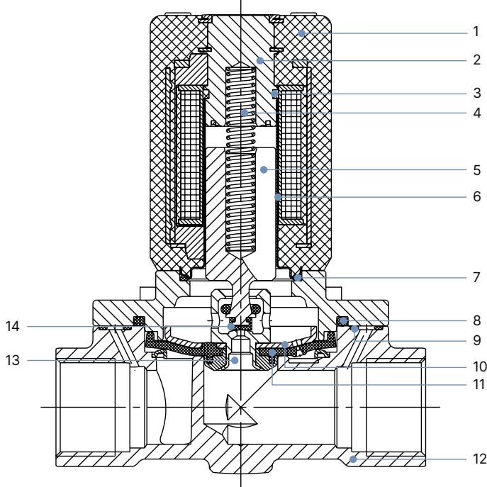
| No. | Element | Material |
|---|---|---|
| 1 | Coil | Epoxy |
| 2 | Stopper | Stainless steel 1.4105, 1.4113 or 1.4523 (optional) |
| 3 | Shading ring (AC variant only) | Brass variant: copper Stainless steel variant: silver |
| 4 | Spring | Stainless steel 1.4310 |
| 5 | Magnetic core | Stainless steel 1.4105 or 1.4113 |
| 6 | Core guide tube | Stainless steel 1.4303 |
| 7-9 | O-ring | NBR, FKM, EPDM |
| 10 | Diaphragm plate | Brass variant: CuZn37 Stainless steel variant: 1.4401 |
| 11 | Diaphragm | NBR, FKM, EPDM |
| 12 | Body | Brass or stainless steel 1.4581 |
| 13 | Pilot valve seat | Brass variant: MS Stainless steel variant: 1.4401 |
| 14 | Seat seal | NBR, FKM, EPDM |
INFO
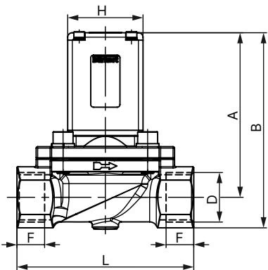
| DN | A | B | G (D1) | G (F1) | NPT (D2) | NPT (F2) | E | L | SW | J | H |
|---|---|---|---|---|---|---|---|---|---|---|---|
| 12 | 80 | 94 | G 1/2 | 14 | NPT 1/2 | 13.7 | 40 | 74.5 | 27 | 81 | 40 |
| 20 | 106 | 122 | G 3/4 | 16 | NPT 3/4 | 14 | 60 | 100 | 32 | 93 | 49 |
| 25 | 110.5 | 131 | G 1 | 18 | NPT 1 | 16.8 | 70 | 115 | 41 | 98 | 49 |
| 32 | 120 | 145 | G 1 1/4 | 20 | NPT 1 1/4 | 17.3 | 85 | 126 | 50 | 106 | 49 |
| 40 | 124 | 154 | G 1 1/2 | 22 | NPT 1 1/2 | 17.3 | 85 | 126 | 60 | 106 | 49 |
| 50 | 176 | 211 | G 2 | 24 | NPT 2 | 17.6 | 115 | 164 | 70 | 133 | 72 |
| 65 | 176 | 218.5 | G 2 1/2 | 27 | NPT 2 1/2 | 23.6 | 115 | 179 | 85 | 133 | 72 |
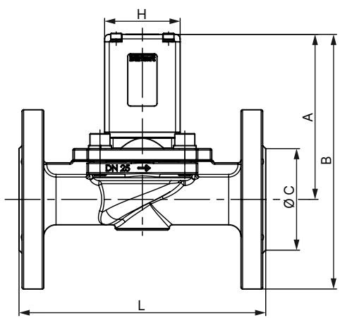
| DN | A | B | C | E | ∅ G | L | M | K | J | H |
|---|---|---|---|---|---|---|---|---|---|---|
| 25 | 110.5 | 170.5 | 68 | 70 | 120 | 160 | 14 | 85 | 98 | 49 |
| 32 | 120 | 190 | 78 | 85 | 140 | 180 | 18 | 100 | 106 | 49 |
| 40 | 126 | 201 | 88 | 85 | 150 | 200 | 18 | 110 | 106 | 49 |
| 50 | 176 | 258.5 | 102 | 115 | 165 | 230 | 18 | 125 | 133 | 72 |
| Orifice [mm] | Kv value water [m³/h] | Port connection | Inrush power AC [VA] | Inrush power AC/DC [W] | Holding power AC [VA/W] | Holding power AC/DC [W] | Weight [kg] |
|---|---|---|---|---|---|---|---|
| 12 | 1.8 | G 1/2 | 100 | 80 | 25/10 | 6 | 1.0 |
| 20 | 6.5 | G 3/4 | 120 | 100 | 32/16 | 9 | 1.4 |
| 25 | 10.0 | G 1 | 120 | 100 | 32/16 | 9 | 1.8 |
| 32 | 16.0 | G 1 1/4 | 120 | 100 | 32/16 | 9 | 2.7 |
| 40 | 16.0 | G 1 1/2 | 120 | 100 | 32/16 | 9 | 3.1 |
| 50 | 38.0 | G 2 | - | 30 | - | 30 | 6.5 |
Dirt Trap Recommendation
For safe operation of the solenoid valve, a dirt trap (≤400µm) must be installed before the valve inlet. For devices with approval according to the European Gas Appliances Directive, installation of the filter is mandatory.
Danger - High Pressure
Before loosening lines or valves, switch off the pressure and drain the lines.
Electrical Safety
Before accessing the device or the system, switch off the power supply and secure it to prevent reactivation. Always connect the protective conductor and check the protective conductor function after installing the coil.
Explore similar products in our catalog