Repairable

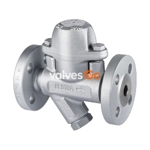
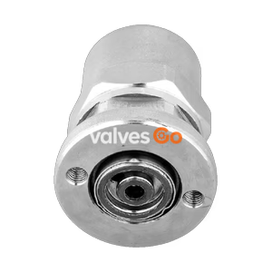
The Spirax Sarco BPW32 is a compact, maintainable stainless steel balanced pressure wafer steam trap for pressures up to 21 bar g, featuring an internal strainer.
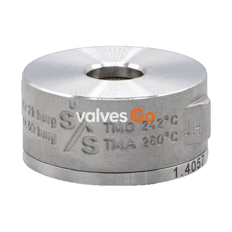
The Spirax Sarco BPW32 is a compact wafer pattern stainless steel balanced pressure steam trap for pressures up to 21 bar g (304.5 psi g). It has an internal strainer, is maintainable and is suitable for installation between two pipeline flanges. It offers both weight and space savings over conventional traps.
The operating element is a capsule containing a small quantity of a special liquid with a boiling point below that of water. In cold conditions at start-up, the capsule is relaxed, and the valve is wide open, allowing unrestricted removal of air. As condensate passes through, heat is transferred to the liquid in the capsule, causing it to expand and shut the trap before steam reaches it.
This product fully complies with the requirements of the European Pressure Equipment Directive 2014/68/EU and falls within category SEP (Group 2 Gases/Liquids). It is available with certification to EN 10204 3.1 (must be stated at the time of order placement).
DN15, DN20 and DN25 to fit between standard flanges PN40, ANSI 150, ANSI 300, JIS 10, JIS 16 and JIS 20.
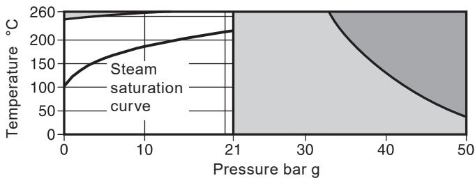
Operating Range
The product must not be used in the dark shaded region. The product should not be used in the light shaded region or beyond its operating range as damage to the internals may occur.
| Body design conditions | PN50 / ANSI 300 |
|---|---|
| PMA Maximum allowable pressure | 50 bar g @ 38 °C (725 psi g @ 100 °F) |
| TMA Maximum allowable temperature | 260 °C @ 33 bar g (500 °F @ 478 psi g) |
| Minimum allowable temperature | 0 °C (32 °F) |
| PMO Maximum operating pressure | 21 bar g @ 260 °C (304 psi g @ 500 °F) |
| TMO Maximum operating temperature | 260 °C @ 21 bar g (500 °F @ 304 psi g) |
| Minimum operating temperature | 0 °C (32 °F) |
Note: For lower operating temperatures consult Spirax Sarco. Designed for a maximum cold hydraulic test pressure of 75 bar g (1088 psi g).
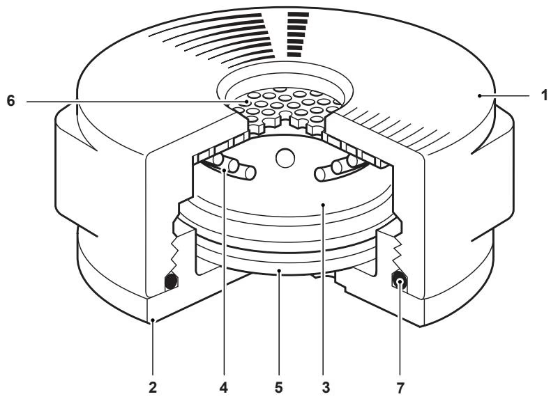
| No. | Part | Material | Standard |
|---|---|---|---|
| 1 | Body | Stainless steel | DIN 17445 1.4408 / ASTM A351 CF8M |
| 2 | Cap | Stainless steel | EN10088 1.4057 / ASTM A479 431 |
| 3 | Capsule | Stainless steel | - |
| 4 | Spring | Stainless steel | BS 2056 302 S26 |
| 5 | Spacer plate | Stainless steel | BS 1449 304 S16 |
| 6 | Strainer screen (0.8 mm perforations) | Stainless steel | ASTM A240 316L |
| 7 | 'O' ring | EPDM | - |
(approximate in mm and kg)
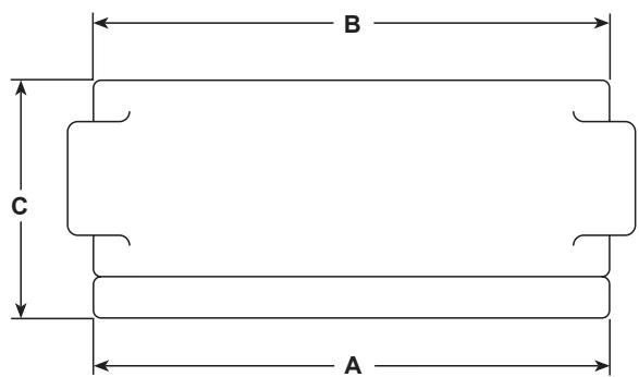
| Size | PN40 A | ANSI 150 A | ANSI 300 A | JIS A | ANSI 150 B | ANSI 300 / PN40 / JIS B | ANSI 150 C | ANSI 300 / PN40 / JIS C | Weight |
|---|---|---|---|---|---|---|---|---|---|
| DN15 | 53 | - | 55 | 58 | 47 | 53 | 25.5 | 25.5 | 0.30 |
| DN20 | 63 | 53 | 67 | 63 | 53 | 63 | 25.5 | 31.5 | 0.57 |
| DN25 | 72 | 53 | 72 | 74 | 62 | 72 | 31.5 | 35.5 | 0.83 |
Installation Orientation
The BPW32 is intended for installation in a vertical line with flow from top to bottom; this will ensure that it is self-draining. It can also be installed in other planes if required. Standard flange gaskets are to be used (supplied by customer).
If the trap is to discharge to atmosphere, ensure it is to a safe place, as the discharging fluid may be at a temperature of 100 °C (212 °F).
Before undertaking any maintenance on the trap, it must be isolated from the supply line and return line, and any pressure allowed to safely normalise to atmosphere. The trap should then be allowed to cool.
To replace the internals set, unscrew the cap (2) from the body (1) and lift out the spacer plate (5), capsule (3), spring (4) and screen (6). Lugs are provided on the side of the body for easy location during disassembly. Insert the new internal set together with the spacer plate (5) which is reusable. Refit the cap (2) using a two-pin spanner. The thread should be coated with a small amount of anti-seize lubricant.
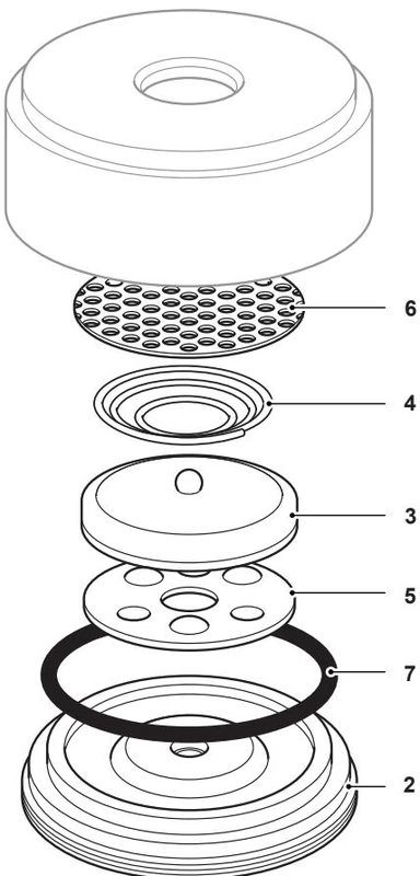
Available Spares:
(Note: Parts drawn in a solid grey line are not supplied as spares. A standard capsule (STD) will be supplied unless specified otherwise on the order.)
Recommended Tightening Torques:
| Item | Connections | Sizes | Torque (N m) | Torque (lbf ft) |
|---|---|---|---|---|
| 1 and 2 | ANSI 150 | All sizes | 10 - 15 | 7.2 - 10.7 |
| PN40, ANSI 300 | DN15 | 10 - 15 | 7.2 - 10.7 | |
| JIS 10, JIS 16 | DN20 | 15 - 20 | 10.7 - 14.3 | |
| JIS 20 | DN25 | 20 - 25 | 14.3 - 17.8 |
Explore similar products in our catalog