


PN25

TLV COSR-3 and COSR-16 self-actuated steam pressure reducing valves with shock-absorbing piston. Features accurate control for process steam systems up to 16 barg.
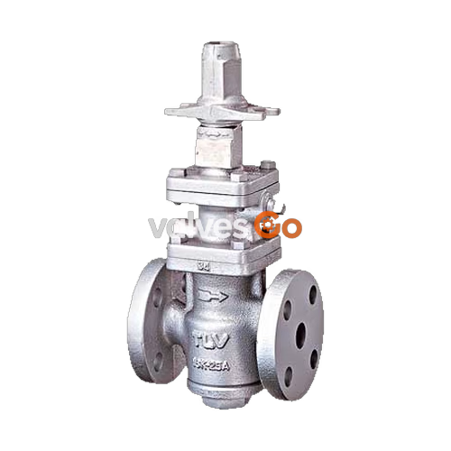
The TLV COSR-3 and COSR-16 are self-actuated pressure reducing valves with a shock-absorbing piston, designed for accurate control in process steam systems. Steam-using equipment can perform its intended operation only when dry saturated steam is available. The COSR series helps eliminate problems caused by entrained condensate by supplying dry saturated steam at a constant pressure at all times.
Technologically advanced, pilot operated pressure reducing valve for accurate control in process steam systems.
WARNING
To avoid malfunctions, product damage, accidents or serious injury, install properly and DO NOT use this product outside the specification range. Local regulations may restrict the use of this product to below the conditions quoted.
Acceptable Operating Range
| Model | COSR-3 | COSR-16 |
|---|---|---|
| Primary Pressure Range (barg) | 1 to 3 | 2 to 16 |
| Secondary Pressure Adjustable Range | 0.1 to 0.5 barg (Minimum 0.3 barg) | Within 10 to 84% of primary pressure (Minimum 0.55 barg) |
| Pressure Differential | 0.7 to 8.5 barg | Maximum 8.5 bar |
| Minimum Adjustable Flow Rate | 5% of rated flow rate | 5% of rated flow rate; 10% for sizes 65 mm and larger |
Specifications
| Model | COSR-3 | COSR-16 |
|---|---|---|
| Body Material | Cast Iron, Ductile Cast Iron, Cast Stainless Steel | Cast Iron, Ductile Cast Iron, Cast Stainless Steel |
| Connection | Screwed, Flanged | Screwed, Flanged |
| Size | 1/2" to 1", DN 20 to 50 | 1/2" to 1", DN 15 to 150 |
| Max. Operating Pressure (PMO) | 3 barg | 16 barg (13 barg for Cast Iron) |
| Max. Operating Temperature (TMO) | 200 °C / 220 °C | 200 °C / 220 °C |
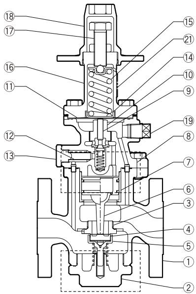
| No. | Description | Material |
|---|---|---|
| 1 | Main Body | Ductile Cast Iron / Cast Stainless Steel / Cast Iron |
| 2 | Cover Plug / Cover | Same material as main body |
| 3 | Main Valve Seat | Stainless Steel |
| 4 | Main Valve | Stainless Steel |
| 5 | Main Valve Holder | Stainless Steel |
| 6 | Piston | Stainless Steel |
| 7 | Cylinder | Stainless Steel |
| 8 | Pilot Body | Same material as main body |
COSR-3 Capacity (kg/h)
| Primary Steam Pressure (barg) | Secondary Steam Pressure (barg) | DN 20 | DN 25 | DN 32 | DN 40 | DN 50 |
|---|---|---|---|---|---|---|
| 1 to less than 2 | 0.5 | 120 | 180 | 540 | 750 | 950 |
| 0.4 | 130 | 190 | 520 | 700 | 920 | |
| 0.3 | 135 | 195 | 510 | 680 | 900 | |
| 2 to 3 | 0.5 | 240 | 340 | 540 | 750 | 950 |
| 0.4 | 230 | 330 | 520 | 700 | 920 | |
| 0.3 | 240 | 340 | 510 | 680 | 900 |
Cv & Kvs Values
| DN 15 | DN 20 | DN 25 | DN 32 | DN 40 | DN 50 | DN 65 | DN 80 | DN 100 | DN 150 | |
|---|---|---|---|---|---|---|---|---|---|---|
| Kvs (DIN) | 3.3 | 5.9 | 9.5 | 13.3 | 20.6 | 31.9 | 50.8 | 72.9 | 110 | 236 |
| Cv (US) | 3.8 | 6.9 | 11.1 | 15.5 | 24.0 | 37.2 | 59.3 | 85.0 | 128 | 275 |
INFO
The Cv & Kvs values shown are for the valve in the full open position. These values are not to be used for COSR sizing, and instead may be used as one of the factors in calculations for safety valve selection.
Screwed
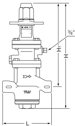
| Size | L (mm) | H (mm) | H1 (mm) | Weight (kg) |
|---|---|---|---|---|
| 1/2", 3/4" | 175 | 357 | 285 | 8.2 |
| 1" | 190 | 357 | 282 | 8.4 |
Flanged
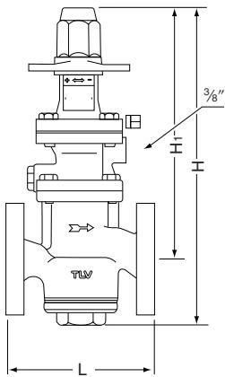
| DN | L (DIN 2501) (mm) | H (mm) | H1 (mm) | Weight (kg) |
|---|---|---|---|---|
| 15 | 130 | 357 | 285 | 8.8 |
| 20 | 150 | 357 | 285 | 9.5 |
| 25 | 160 | 357 | 282 | 11 |
| 32 | 180 | 385 | 302 | 16 |
| 40 | 200 | 385 | 302 | 17 |
| 50 | 230 | 412 | 315 | 26 |
WARNING
Installation, inspection, maintenance, repairs, disassembly, adjustment and valve opening/closing should be carried out only by trained maintenance personnel. Install for use under conditions in which no freeze-up will occur and no water hammer will occur.
If the COSR is installed either directly before or after an elbow or control valve, unevenness in flow may result in chattering and unstable pressure. To ensure stable steam flow, it is recommended that the COSR be installed on straight runs of piping.
A control valve (i.e. for temperature control) installed between the COSR and the steam equipment may raise pressure between the COSR and the control valve when closed. The control valve should be installed close to the steam-using equipment, and a safety valve should be installed downstream of the control valve.
A strainer should be installed ahead of the COSR. The strainer should be 60 mesh or finer, installed horizontally and at 90° to its normal orientation to the pipeline, in order to prevent condensate accumulation in the screen body.
Explore similar products in our catalog




