PN16

TLV JH8R-X inline repairable free float steam trap with thermostatic air venting. Designed for small-to-large capacities with pressures up to 3.2 MPaG (450 psig).
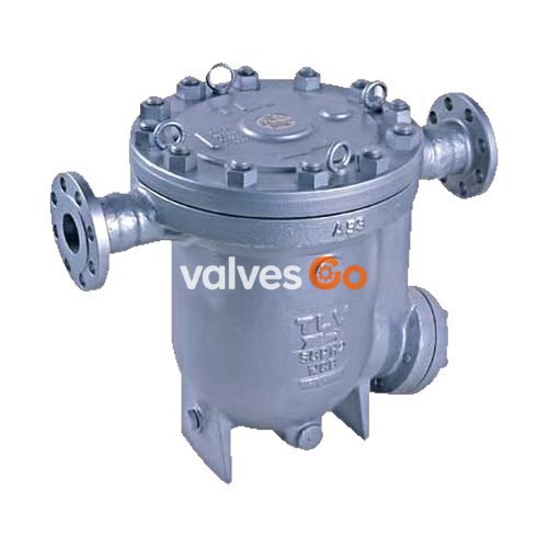
TLV JH8R-X inline repairable free float steam trap with thermostatic air vent (X-element) is suitable for a wide range of applications with small-to-large capacities and pressures up to 3.2 MPaG (450 psig), such as all kinds of heat exchangers, process heaters and coils. The trap discharges condensate continuously and automatically, at a temperature slightly lower than saturation temperature.
DANGER
NEVER apply direct heat to the float. The float may explode due to increased internal pressure, causing accidents leading to serious injury or damage to property and equipment.
WARNING
Install properly and DO NOT use this product outside the recommended operating pressure, temperature and other specification ranges. Improper use may result in such hazards as damage to the product or malfunctions, which may lead to serious accidents. DO NOT use this product in excess of the maximum operating pressure differential. Such use could make discharge impossible.
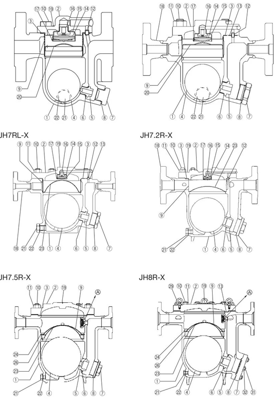
Note: For full part details, refer to the manufacturer documentation.

INFO
Maximum allowable pressure (PMA) and maximum allowable temperature (TMA) are PRESSURE SHELL DESIGN CONDITIONS, NOT OPERATING CONDITIONS.

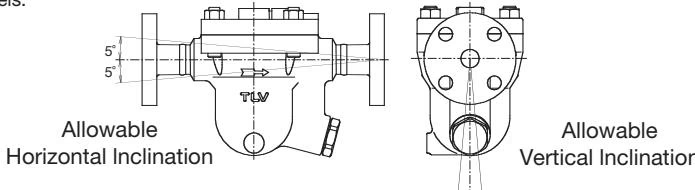
Check to make sure that the pipes connected to the trap have been installed properly.
Operational inspections should be performed at least twice per year, or as called for by trap operating conditions. Steam trap failure may result in temperature drop in the equipment, poor product quality or losses due to steam leakage.
WARNING
Before attempting to open the trap, close the inlet and outlet isolation valves and wait until the trap has cooled completely. Failure to do so may result in burns.
| Parts Inspection Procedure | |
|---|---|
| Body, Cover(s) | Check inside for damage, dirt, grease, oil film, rust or scale |
| Gaskets | Check for warping or damage |
| X-element | Check for damage |
| Screen(s) | Check for clogging, corrosion or damage |
| Float | Check for deformation, damage, oil film or water inside |
| Air Vent Valve Seat, Orifice | Check for rust, scale, oil film, wear or damage |
A visual inspection can be carried out to aid in determining the necessity for immediate maintenance or repair, if the trap is open to atmosphere. If the trap does not discharge to atmosphere, use diagnostic equipment such as TLV TrapMan or TLV Pocket TrapMan.
| Status | Description |
|---|---|
| Normal: | Condensate is discharged continuously with flash steam and the sound of flow can be heard. If there is very little condensate, there is almost no sound of flow. |
| Blocked: | No condensate is discharged. The trap is quiet and makes no noise, and the surface temperature of the trap is low. |
| Blowing: | Live steam continually flows from the outlet and there is a continuous metallic sound. |
| Steam Leakage: | Live steam is discharged through the trap outlet together with the condensate and there is a high-pitched sound. |