Repairable

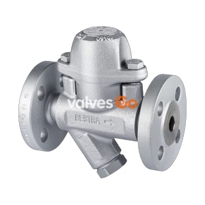
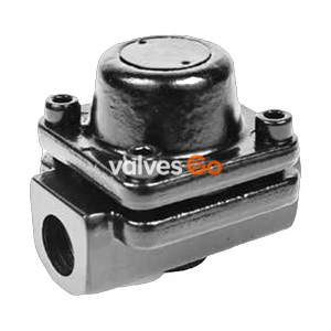
TLV LV13N brass balanced pressure thermostatic steam trap with fail-open design for medium capacity applications up to 2.1 MPaG.
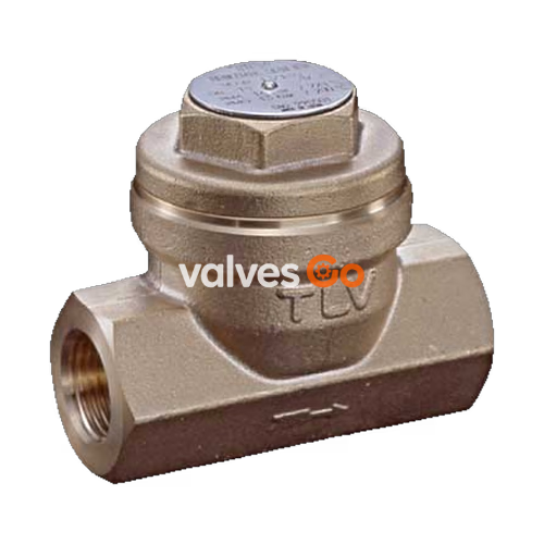
The TLV LV13N is a brass balanced pressure thermostatic steam trap designed with a "fail-open" feature. It is suitable for medium capacity applications up to 0.5, 0.8, 1.3, or 2.1 MPaG (75, 115, 185, or 300 psig). The LV13N is primarily utilized for steam-using equipment that discharges condensate at temperatures slightly below saturation temperature, such as tracer lines, vessels, and heaters.
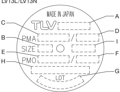
The nameplate specifies the exact maximum allowable and operating conditions. Maximum allowable pressure (PMA) and maximum allowable temperature (TMA) are pressure shell design conditions, not operating conditions.
WARNING
To avoid malfunctions, product damage, accidents or serious injury, do not use the product outside the specification ranges.
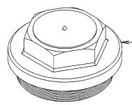
The LV13N features a brass body and cover, housing the internal components necessary for its thermostatic operation.
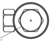
| No. | Description | Replacement Part |
|---|---|---|
| 1 | Body | |
| 2 | Cover | |
| 3 | X-element | √ |
| 4 | Valve Seat | √ |
| 5 | Screen | √ |
| 6 | Nameplate | |
| 7 | Spring Clip | √ |
| 8 | Cover Gasket | √ |
| 9 | X-element Guide | √ |
Note: Replacement parts marked with √ are available in the repair kit.
Proper installation and piping ensure the longevity and efficiency of the steam trap.
Visual inspection can help determine the necessity for maintenance if the trap discharges to the atmosphere.
| State | Description |
|---|---|
| Normal | Condensate is discharged intermittently with flash steam and the sound of flow can be heard. |
| Blocked | No condensate is discharged. The trap makes no noise and the surface temperature is low. |
| Blowing | Live steam continually flows from the outlet, potentially with a high-pitched whistling sound. |
| Steam Leakage | Live steam is discharged with condensate, potentially with a high-pitched whistling sound. |
INFO
Flash steam is sometimes mistaken for steam leakage during visual inspections. Diagnostic instruments like the TLV TrapMan are recommended.
Operational inspections should be performed at least twice per year. The LV13N can be maintained without being removed from the pipeline, provided the surrounding pipes are securely supported.
Before opening the trap, close the isolation valves and wait until it cools to room temperature.
| Part | Disassembly | Reassembly |
|---|---|---|
| Cover (2) | Use an open-end wrench to remove. | Clean seating surfaces; tighten to 80 N·m (59 lbf·ft) torque. |
| Cover Gasket (8) | Remove carefully. | Replace with a new gasket only if worn or damaged. |
| Spring Clip (7) | Use pliers to remove. | Insert securely into the 3 slots in the guide. |
| X-element (3) | Grasp the ball at the tip with pliers to remove. | Insert right side up; ensure it does not catch on the guide. |
| Valve Seat (4) | Use a socket wrench to remove. | Do not coat threads with anti-seize; tighten to 35 N·m (26 lbf·ft) torque. |
| X-element Guide (9) | Be careful not to bend the guide. | Fix with Valve Seat and ensure the X-element inserts smoothly. |
| Screen (5) | Be careful not to bend the screen. | Be careful not to bend the screen. |
| Problem | Possible Cause | Remedy |
|---|---|---|
| Blocked or Poor Discharge | X-element stuck to valve seat, clogged seat, or clogged screen. | Clean the components. |
| Steam-locking. | Perform bypass blowdown or allow trap to cool. | |
| Operating pressure exceeds maximum. | Study inlet pressure. | |
| Steam Leakage or Blow-off | Valve closure obstructed by rust. | Clean (inspect screen). |
| Worn or damaged X-element or Valve Seat. | Replace X-element or Valve Seat. | |
| Cover loose or gasket damaged. | Tighten cover or replace gasket. |
Explore similar products in our catalog