All-Stainless Steel Material

TLV SA3 micro air vent series (SA3-3, SA3-10) designed for water-bearing pipes. Features up to 1.0 MPaG operating pressure and 100°C maximum operating temperature.
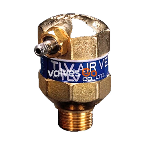
The TLV SA3 is a micro air vent designed for use on water-bearing pipes. It automatically discharges accumulated air from piping systems and should not be used on steam lines. The series includes the SA3-3 and SA3-10 models, suitable for different pressure ranges.
CAUTION
| Model | SA3-3 | SA3-10 |
|---|---|---|
| Maximum Operating Pressure (PMO) | 0.3 MPaG (3.0 barg / 45 psig) | 1.0 MPaG (10 barg / 150 psig) |
| Minimum Operating Pressure | 0.01 MPaG (0.1 barg / 1.5 psig) | 0.1 MPaG (1.0 barg / 15 psig) |
| Maximum Operating Temperature (TMO) | 100 °C / 212 °F | 100 °C / 212 °F |
| Maximum Allowable Pressure (PMA)* | 1.0 MPaG (10 barg / 150 psig) | 1.0 MPaG (10 barg / 150 psig) |
| Maximum Allowable Temperature (TMA)* | 100 °C / 212 °F | 100 °C / 212 °F |
Maximum allowable pressure (PMA) and maximum allowable temperature (TMA) are PRESSURE SHELL DESIGN CONDITIONS (NOT OPERATING CONDITIONS).
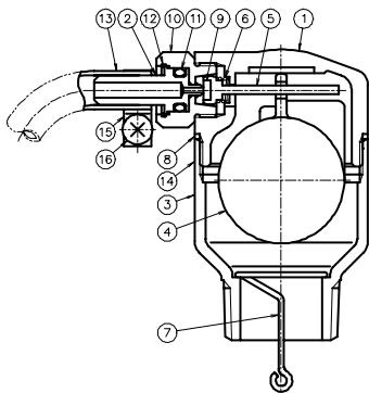
| No. | Name | No. | Name |
|---|---|---|---|
| 1 | Body | 10 | Valve Seat Holder |
| 2 | Valve Seat | 11 | O-Ring |
| 3 | Base | 12 | Snap Ring |
| 4 | Float | 13 | Vinyl Tube |
| 5 | Valve Holder | 14 | Nameplate |
| 6 | Coil Spring | 15 | Worm Drive Clamp |
| 7 | Siphon Rod | 16 | Clamp Screw |
| 8 | Body Gasket | ||
| 9 | Valve |
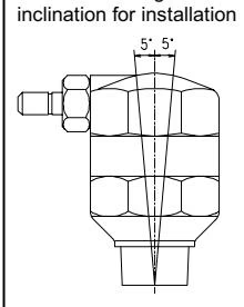
Use the following procedures to remove components. Use the same procedures in reverse to reassemble.
| Part | During Disassembly | During Reassembly |
|---|---|---|
| Base | Remove with a 32 mm (1¼") wrench | Tighten to a torque of 15 N·m (11 ft·lbf) |
| Body Gasket | Remove the gasket | Replace with a new gasket |
| Siphon Rod | Remove siphon rod from base | Attach the siphon rod to the base |
| Vinyl Tube, Worm Drive Clamp | Loosen the clamp screw with a Phillips screwdriver and remove the worm drive clamp; remove the vinyl tube from the valve seat | Reattach the vinyl tube to the valve seat, fasten with the worm drive clamp; tighten the clamp screw with a Phillips screwdriver |
| Valve Seat Holder | Remove with a 12 mm (½") wrench | Tighten to a torque of 8 N·m (5.9 ft·lbf) |
| Valve Holder (Valve), Coil Spring | Remove from the body | Insert the valve holder into the body's outlet and into the hole in the float |
| Float | Remove from the body | Place in body, align hole with outlet |
| Snap Ring | Remove with a needle-nose pliers | Insert securely into the slot |
| Valve Seat | Remove from the valve seat holder | Be careful not to damage the seating surface |
| O-Ring | Remove the O-Ring | Replace with a new O-Ring |
Note: 1 N·m ≈ 10 kg·cm
When the air vent fails to operate properly, use the following table to locate the cause.
| Problem | Cause | Remedy |
|---|---|---|
| No air discharged or discharge is poor | Air is not reaching the vent because the water in the piping is not being displaced by air | Make sure that the inlet piping is 15 mm (½") or larger |
| The valve seat is clogged | Clean the valve seat | |
| The inlet or outlet piping is clogged | Clean the piping | |
| The operating pressure exceeds the rated maximum operating pressure | Replace the air vent with a model with a more suitable operating pressure | |
| Water leaks when the valve is closed | The valve seat is clogged with dirt or scale or is damaged | Clean the valve seat or replace it with a new valve seat |
| Improper installation | Correct the installation | |
| Valve does not close and water spurts out | Specific gravity of the liquid is not suitable for this product | Select a product with suitable specifications for the operating conditions (consult TLV) |
Explore similar products in our catalog