All-Stainless Steel Material

Yoshitake TA-16CVS Air Vent Valve. Features a stainless steel body, FKM valve disc, straight check valve joint, and handles 0.01-1.0 MPa working pressure.
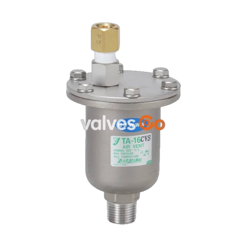
Yoshitake TA-16CVS is a stainless steel air vent valve designed for building equipment, industrial equipment, and building complexes. It is part of the TA-16 series, which is essential for air-conditioning piping systems because air mixed in the piping can lead to a decline in heat-effectiveness, noise production, or equipment corrosion. The TA-16CVS features a compact body and a straight-type check valve joint, ensuring automatic air discharge without sucking in outside air when the equipment stops operating.
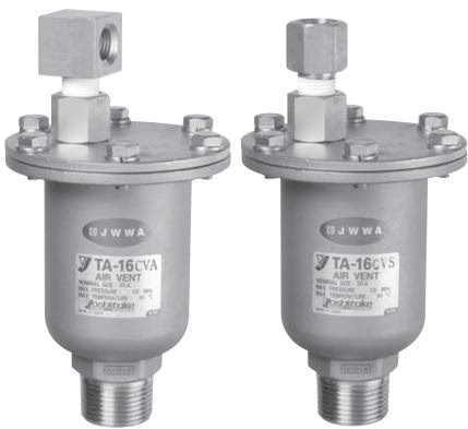
| Model | TA-16 | TA-16L | TA-16CVA | TA-16CVS |
|---|---|---|---|---|
| Nominal size | 15-25A | 15-25A | 15-25A | 15-25A |
| Application | Cold and hot water | Cold and hot water | Cold and hot water | Cold and hot water |
| Working pressure | 0.01-1.0 MPa | 0.01-1.0 MPa | 0.01-1.0 MPa | 0.01-1.0 MPa |
| Check valve | No | No | Provided | Provided |
| Maximum temperature | 90°C | 90°C | 90°C | 90°C |
| Body, cover, float | Stainless steel | Stainless steel | Stainless steel | Stainless steel |
| Valve disc, gasket | FKM | FKM | FKM | FKM |
| Check valve joint | - | - | FKM (fluororubber) | FKM (fluororubber) |
| Inlet Connection | JIS R screwed | JIS R screwed | JIS R screwed | JIS R screwed |
| Outlet Connection | JIS Rc 1/4 screwed | Φ6 (hose inside diameter) | JIS Rc 1/4 screwed | JIS Rc 1/4 screwed |
INFO
The TA-16CVS check valve closing pressure is -0.005 MPa or less.
TA-16CVS Dimensions: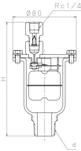
| Nominal size | d | H | Weight (kg) |
|---|---|---|---|
| 15A | R 1/2 | 142 | 0.70 |
| 20A | R 3/4 | 144 | 0.72 |
| 25A | R 1 | 148.5 | 0.78 |
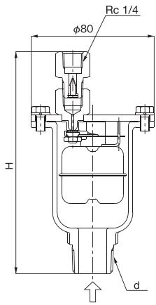
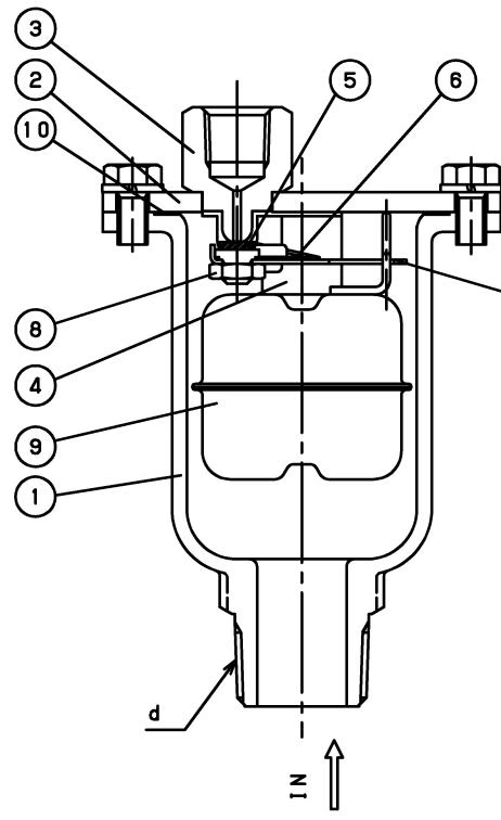
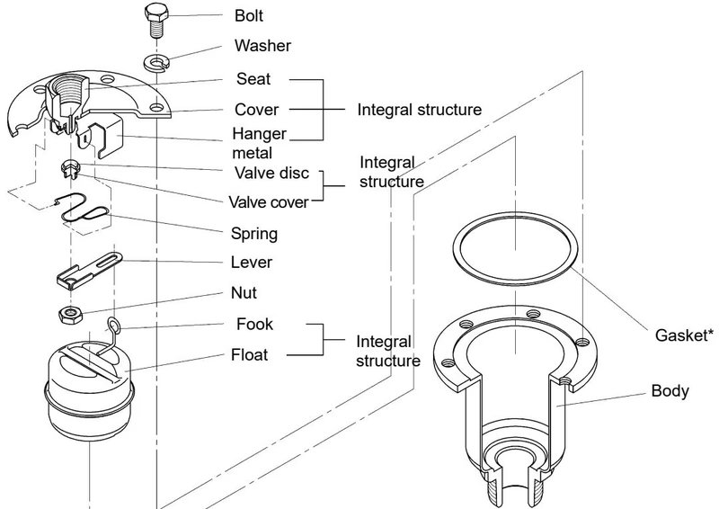
| No. | Main parts |
|---|---|
| 1 | Body |
| 2 | Cover |
| 3 | Seat (Exhaust outlet) |
| 4 | Hanger Metal |
| 5 | Valve Disc |
| 6 | Spring |
| 7 | Lever |
| 8 | Nut |
| 9 | Float |
| 10 | Gasket |
| 11 | Bolt |
| 12 | Label |
Available optional parts for exhaust outlet connections include:
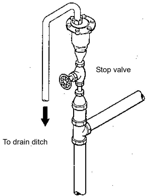
Installation Precautions
Operation Note
A small amount of water may blow out with air at air discharge during initial operation. This is not a failure of the product.
Troubleshooting:
| Trouble | Cause | Remedy |
|---|---|---|
| No air discharge | 1. The stop valve on inlet side is kept closed. 2. Internal piping pressure is more than appropriate value. 3. Air accumulates too slowly. | 1. Open the stop valve fully. 2. Lower the internal piping pressure, or replace the valve. 3. Install the valve on a place where air is easy to accumulate. |
| Water blowout from Exhaust outlet | 1. Foreign substances exist on the valve disc and seat. 2. The float is damaged. | 1. Remove and clean the valve disc and seat. 2. Replace the float. |
| External leakage | 1. Damage or deformation of the body or cover. 2. Gasket is damaged. | 1. Replace the product. 2. Replace the gasket. |
| Sucking in air outside | 1. Foreign substances exist on the check valve. | 1. Remove foreign substances. |
Yoshitake Air & Gas Vents
TA, TAV, and VB series air and vacuum valves for automatic venting, rapid air release, and vacuum protection.
Explore similar products in our catalog