Cast Iron

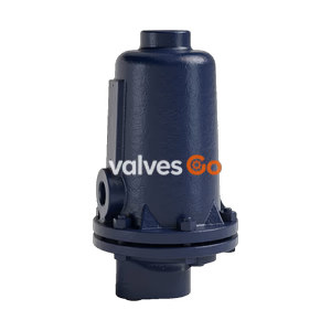
Yoshitake TSF-11AT float and bucket type air trap for effective condensate discharge. Features ductile cast iron body, stainless steel float, and 2.1 MPa maximum pressure.
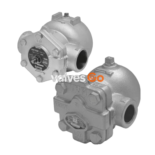
Yoshitake TSF-11AT is an air trap suitable for discharging condensate. It utilizes a float mechanism and is capable of handling maximum working differential pressures up to 2.1 MPa. The product is designed with a ductile cast iron body and stainless steel main components, offering excellent durability and corrosion resistance.
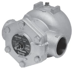
| Model | TSF-11AT |
|---|---|
| Nominal size | 32A-50A |
| Application | Condensate / Air, Other non-dangerous fluid |
| Working pressure | TSF-11AT-5: 0.01-0.5 MPa TSF-11AT-10: 0.01-1.0 MPa TSF-11AT-21: 0.01-2.1 MPa |
| Maximum temperature | 220℃ |
| Material (Body) | Ductile cast iron |
| Material (Float) | Stainless steel |
| Material (Valve, valve seat) | Stainless steel |
| Connection | JIS Rc screwed, NPT screwed |
Flow Direction
The flow direction when shipping is adjusted from left to right. When using from right to left, the direction can be adjusted by turning the cock. Due to the connection of the pressure equalization pipe, flow direction from top to bottom is not available.
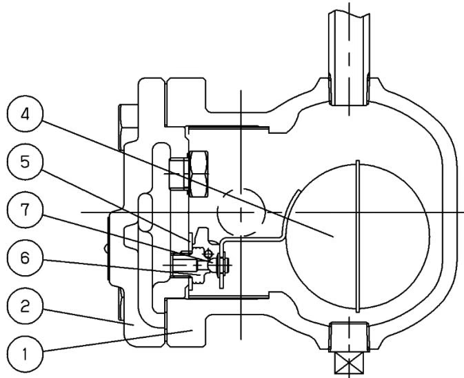
| No | Parts name |
|---|---|
| ① | Body |
| ② | Cover |
| ④ | Float(P) |
| ⑤ | Float holder |
| ⑥ | Valve seat |
| ⑦ | Valve |
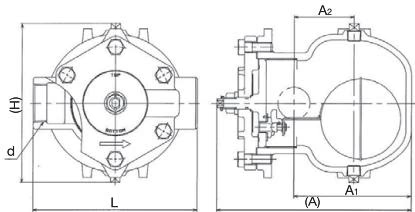
| Nominal size | d | L | A | A1 | A2 | H | Plug | Weight (kg) |
|---|---|---|---|---|---|---|---|---|
| 32A | Rc or NPT 1 1/4 | 190 | 244 | 147 | 75 | 210 | Rc or NPT 3/8 | 10.0 |
| 40A | Rc or NPT 1 1/2 | 205 | 244 | 147 | 75 | 210 | Rc or NPT 3/8 | 10.2 |
| 50A | Rc or NPT 2 | 220 | 244 | 147 | 75 | 210 | Rc or NPT 3/8 | 10.5 |
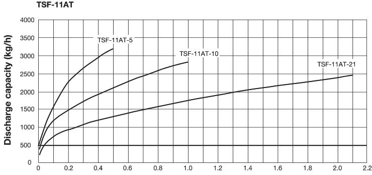
Safety Factor
The discharge capacity shown in the charts is the maximum value. In designing a system, select an air trap with a sufficient safety factor (more than two times the regular level).
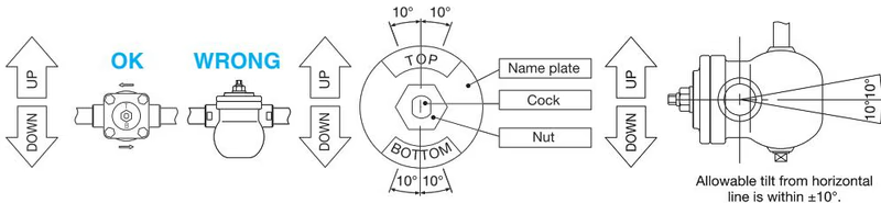
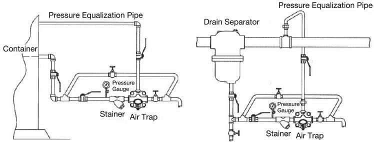
Installation Cautions
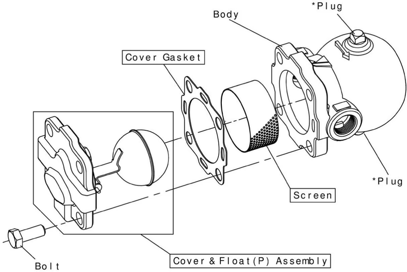 *Remove the plug on the "TOP" side and install an equalizing line.
Yoshitake Compressed Air Drain Traps
LD and TSF-AT series compressed-air drain traps for automatic condensate removal from air systems.
Explore similar products in our catalog