


PN25

High-performance externally piloted pressure reducing valve for steam service. Features 20:1 rangeability, high Cv, and carbon steel construction for up to 450 psig.
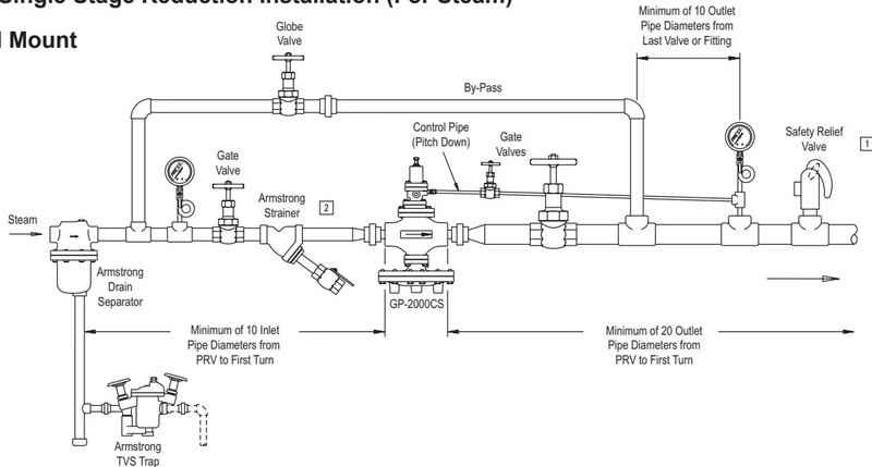
Armstrong GP-2000CS is a high-performance, externally piloted reducing valve for large capacity requirements. Typical use is on intermittent service, including applications such as heat exchangers, steam coils, rotating dryers, process equipment, and heating systems. With a 20:1 rangeability and high Cv, the GP-2000CS is reliable and accurate (+/-1% of pressure set point from 5% to 100% of flow) over a long, trouble-free service life. Stellited stainless steel working parts are renewable in-line. It is single-seated for dead-end service.
| Application | Inlet Pressure psig (bar) | Reduced Pressure psig (bar) | Spring Color | Maximum Temperature | Minimum Differential psig (bar) |
|---|---|---|---|---|---|
| Steam (NPT) | 15 - 450 (1 - 31) | 3 - 21 (.21 - 1.4) | Yellow | 600°F (315°C) | 7 (.48) |
| Steam (150 lb Flanged) | 15 - 140 (1 - 9.6) | 15 - 200 (1 - 13.6) | Green | 600°F (315°C) | 7 (.48) |
| Steam (300 lb Flanged) | 15 - 450 (1 - 31) | 190 - 300 (13.1 - 20.6) | Brown | 600°F (315°C) | 7 (.48) |
Materials:
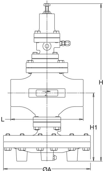
| Size | L (NPT) | L (150#) | L (300#) | A | F | H Integral | H1 | H2 | Weight (NPT) | Weight (150#) | Weight (300#) | Cv |
|---|---|---|---|---|---|---|---|---|---|---|---|---|
| 1/2" (15mm) | 5-15/16" | - | - | 7-15/16" | 6-7/8" | 15-3/4" | 6-3/4" | 9-5/8" | 35 lb | - | - | 5.0 |
| 3/4" (20mm) | 5-15/16" | - | - | 7-15/16" | 6-7/8" | 15-3/4" | 6-3/4" | 9-5/8" | 35 lb | - | - | 7.2 |
| 1" (25mm) | 6-5/16" | - | - | 8-15/16" | 7-1/16" | 15-15/16" | 6-15/16" | 10" | 49 lb | - | - | 10.9 |
| 1-1/4" (32mm) | 7-1/8" | - | - | 8-15/16" | 7-7/16" | 17-1/8" | 7-5/8" | 11-1/8" | 53 lb | - | - | 14.3 |
| 1-1/2" (40mm) | 7-1/8" | - | - | 8-15/16" | 7-7/16" | 17-1/8" | 7-5/8" | 11-1/8" | 53 lb | - | - | 18.8 |
| 2" (50mm) | 9-1/8" | 8-9/16" | 9-1/8" | 10-15/16" | 7-11/16" | 19-5/8" | 8-1/2" | 12-5/8" | 62 lb | 88 lb | 92 lb | 32 |
| 2-1/2" (65mm) | - | 10-15/16" | 11-1/2" | 13-13/16" | 8-5/16" | 21-3/4" | 9-13/16" | 14-3/4" | - | 159 lb | 168 lb | 60 |
| 3" (80mm) | - | 11-3/4" | 12-7/16" | 13-13/16" | 8-3/4" | 22-5/8" | 10-7/16" | 15-3/4" | - | 174 lb | 185 lb | 78 |
| 4" (100mm) | - | 13-1/2" | 14-1/8" | 15-13/16" | 9-7/16" | 25-15/16" | 12-5/8" | 19-1/4" | - | 276 lb | 293 lb | 120 |
WARNING
Improper sizing or adjustment of the pressure reducing valve may cause hunting, scale problems, water hammer, etc., and can heavily damage the main parts of the valve.
Adjustment Procedure:
INFO
Downstream usage must be present in order to set any pressure-reducing valve.
DANGER
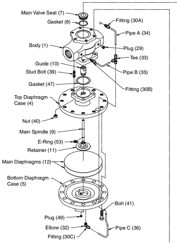
Before disassembly, check to make sure that the valves before and after the reducing valve are closed, including the valve in the control pipe. Also, make sure that the pressure has been relieved and that the valves are holding.
| Problem | Cause | Solution |
|---|---|---|
| Outlet Pressure does not reach desired value. | Inlet pressure is not adequate. | Raise inlet pressure if possible. |
| Adjustment is not proper. | Dismantle and clean. | |
| Orifice is too large or plugged. | Install proper fitting or clean/replace. | |
| Pilot valve is clogged. | Disassemble and clean pilot valve seat. Check screen. | |
| Main diaphragms are damaged. | Disassemble and replace main diaphragms. | |
| Valve size is too small. | Resize and install larger valve. | |
| Secondary pressure exceeds the pressure setting. | Adjustment is not proper. | Readjust. |
| Orifice of fitting is plugged. | Clean or replace fitting. | |
| Dirt caught between main/pilot valve and seat. | Flush out dirt or lap the valve and seat. | |
| Dirt between main spindle and guide. | Clean. | |
| By-pass valve is not shut or is leaking. | Repair or replace. | |
| Sensing line is plugged or not connected. | Clean, replace, or install sensing line properly. | |
| Operation is unstable. | Orifice fitting is partially plugged. | Remove and clean or replace. |
| Sensing pipe installed with too much turbulence. | Install sensing pipe at another location. | |
| Liquid is collecting in sensing line. | Slant pipe away from PRV. | |
| Quick opening/closing valve too close. | Relocate PRV. | |
| Excessive noise is present. | Valve size is larger than required (chatter). | Change valve or add orifice plate to outlet. |
| Pressure reduction ratio exceeds 20:1. | Use two stage reduction. | |
| Fluid velocity is too high. | Resize station using two stage reduction or use sound silencer. | |
| Automatic valve is too close to PRV. | Relocate. |
Explore similar products in our catalog



