


PN25

BURKERT 20012642 (Type 2101) is a pneumatically operated 2/2-way globe valve, DN25 PN25 flanged, stainless steel 316L body, PTFE seat, normally closed (CFA), flow below seat, rated -0.9 to 16 bar and -10 to +185 °C.
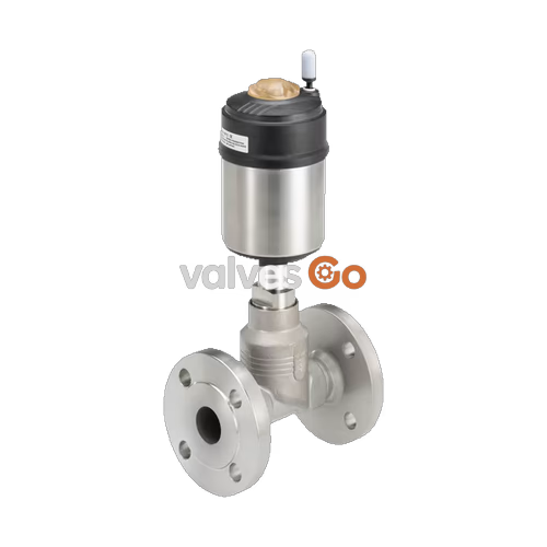
BURKERT 20012642 (Type 2101) is a pneumatically operated 2/2-way globe valve configured for fluid isolation in decentralized automation systems. Built with a cast stainless steel 316L (CF3M) body and DN 25 flange connections conforming to DIN EN 1092-1 PN25, the valve operates with Control Function A (normally closed by spring force). The process fluid flows below the valve seat, closing against the medium flow to prevent water hammer when handling liquid media, steam, and neutral gases. Actuation is driven by a Ø 70 mm (Size M) piston actuator housed in polyphenylene sulphide (PPS) with a stainless steel 1.4561 casing. The sealing system features a PTFE seat seal mounted on an articulated swivel plate, combined with a self-adjusting PTFE V-ring gland packing with spring compensation, providing hermetic tightness to Leakage Rate A per DIN EN 12266-1.

Designed for demanding industrial duties including CIP/SIP cleaning, vacuum service down to -0.9 bar(g), and saturated steam up to +185 °C, the unit provides a water flow factor (Kv) of 13 m³/h. The actuator housing rotates freely through 360°, allowing alignment of pneumatic pilot lines in tight piping installations. Integrated internal pilot air channels enable direct, clean-room compatible mounting of ELEMENT series control heads and digital positioners without external tubing.
| Specification Parameter | Value / Engineering Standard |
|---|---|
| Product Identification | Model 20012642 / Type 2101 |
| Valve Construction | Complete 2/2-way globe valve, ELEMENT architecture |
| Nominal Diameter (Seat / Orifice) | DN 25 (25 mm) |
| Port Connection 1 | Flange DIN EN 1092-1 PN 25 (Face-to-face FTF 1 per DIN EN 558-1) |
| Circuit Function | Control function A (normally closed, NC by spring return) |
| Flow Direction | Below seat (closing against medium flow) |
| Operating Pressure Range | -0.9 bar(g) to 16 bar(g) (vacuum variant included) |
| Nominal Pressure Classification | PN 25 (DIN EN 1333), Class 150 (DIN EN 1759) |
| Minimum Pilot Pressure | 4.8 bar(g) |
| Maximum Pilot Pressure | 10 bar(g) |
| Flow Coefficient (Kv Water) | 13 m³/h (water at +20 °C, 1 bar pressure drop) |
| Seat Leakage Rate | Leakage Rate A according to DIN EN 12266-1 (Air test medium) |
| Maximum Fluid Viscosity | 600 mm²/s |
| Medium Temperature Range | -10 °C to +185 °C |
| Ambient Temperature Range | -10 °C to +100 °C (-10 °C to +60 °C with push-in pilot connector) |
| Actuator Size / Material | Ø 70 mm (Size M) / Polyphenylene sulphide (PPS) with 1.4561 casing |
| Pilot Air Interface | Push-in connector for Ø 6 mm hose (ELEMENT interface) |
| Control Medium | Filtered dry compressed air or neutral gases |
| Degree of Protection | IP65 / IP67 according to IEC 529 / EN 60529, NEMA Type 4X |
| Conformities & Directives | PED 2014/68/EU, Machinery Directive 2006/42/EC, EC 1935/2004 |
| Explosion Protection Marking | EPS 18 ATEX 2 008 X / IECEx EPS 18.0007X (II 2G Ex h IIC T4...T2 Gb, II 2D Ex h IIIC T135°C...T300°C Db) |
All wetted parts comply with European Regulation (EC) 1935/2004 for food contact. Lubricants used in the packing gland and actuator mechanism are rated according to NSF H1.
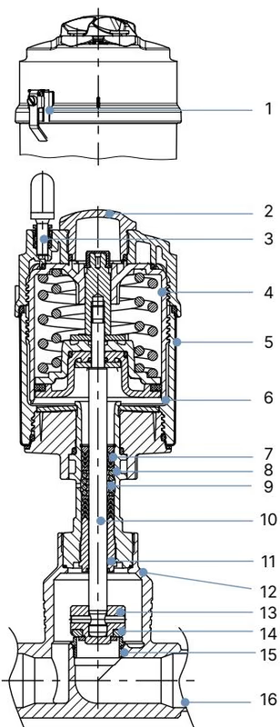
| Item No. | Component Description | Material Specification |
|---|---|---|
| 1 | Ground terminal | Stainless steel 1.4301 / 1.4305 (ATEX configurations) |
| 2 | Optical position indicator | Polysulfone (PSU) |
| 3 | Pilot air port | Polypropylene (PP) push-in fitting (G 1/8 stainless steel optional) |
| 4 | Actuator cover | Polyphenylene sulphide (PPS) |
| 5 | Actuator casing | Stainless steel 1.4561 (316Ti) |
| 6 | Piston seal | Fluoroelastomer (FKM) |
| 7 | Return spring | Stainless steel 1.4310 |
| 8 | Tube | Stainless steel 1.4401 (316) / 1.4404 (316L) |
| 9 | Spindle packing | Filled PTFE V-rings with Belleville spring compensation |
| 10 | Valve spindle (stem) | Stainless steel 1.4401 (316) / 1.4404 (316L) |
| 11 | Spindle guide | Polyether ether ketone (PEEK) for DN 15 to DN 65 |
| 12 | Body seal | Graphite (PTFE optional) |
| 13 | Swivel plate | Stainless steel 1.4401 (316) / 1.4404 (316L) |
| 14 | Seat seal | Virgin PTFE (PEEK optional for high-temperature service) |
| 15 | Valve seat with O-ring | Stainless steel 1.4571 with EPDM O-ring |
| 16 | Valve body | Stainless steel 316L / CF3M |
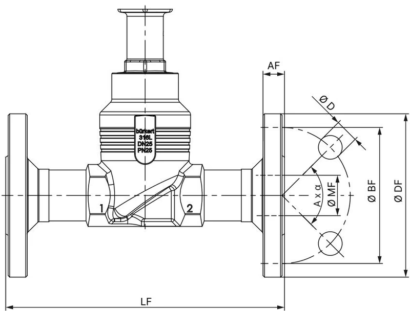
BURKERT 20012642 incorporates a flanged body compliant with DIN EN 1092-1 PN 25, utilizing standard face-to-face dimension series FTF 1 according to DIN EN 558-1.
| Dimensional Parameter | Specification (DN 25) | Dimensional Unit |
|---|---|---|
| Port Nominal Size | DN 25 (1" pipe match) | mm |
| Flange Outer Diameter (Ø DF) | 115 | mm |
| Face-to-Face Overall Length (LF) | 160 | mm |
| Bolt Pitch Circle Diameter (Ø BF) | 85 | mm |
| Flange Thickness (AF) | 18 | mm |
| Bolt Hole Diameter (Ø D) | 14 | mm |
| Bolt Hole Count and Spacing (A × α) | 4 × 90° | Holes / Deg |
| Raised Face Outer Diameter (Ø MF) | 29.7 | mm |
| Actuator Outer Diameter (Ø A) | 91 (Actuator Size 70 / M) | mm |
| Total Height to Centerline (H) | 259 | mm |

In Control Function A with flow below the seat, the valve closes against the incoming line pressure via internal spring force. When pilot pressure is applied to port 1, the piston lifts the spindle and articulated swivel plate. Because the line pressure acts beneath the swivel plate, it assists the opening motion of the valve.
Water Hammer Prevention
Valves with flow direction above the seat generate water hammer when closing against liquid media, causing severe line shock and potential rupture. Model 20012642 is factory-configured for flow below the seat, which eliminates water hammer during closure and permits safe operation across liquids, steam, and gases.
The maximum permissible working pressure decreases with rising fluid temperature in accordance with the pressure-temperature ratings of the valve body and relevant standards:
| Medium Temperature (°C) | DIN EN 12516-1 PN 25 Body (bar) | ASME B16.5 / B16.34 Class 150 (bar) | JIS B 2220 10K (bar) |
|---|---|---|---|
| -10 °C to +50 °C | 25.0 | 18.4 (at +50 °C) / 19.0 (at +38 °C) | 14.0 |
| +100 °C | 24.5 | 16.2 | 14.0 |
| +150 °C | 22.4 | 14.8 | 13.4 |
| +185 °C / +200 °C | 20.3 | 13.7 | 12.4 |
| +230 °C | 19.0 | 12.7 | 11.7 |
For Model 20012642, the operating pressure is capped at 16 bar(g) for Control Function A with a Ø 70 mm actuator on DN 25 at temperatures up to +185 °C. The minimum required pilot pressure is 4.8 bar(g).
Model 20012642 features the Bürkert ELEMENT integrated interface, allowing direct mounting of position feedback indicators and intelligent control heads:
The actuator housing can be turned smoothly through 360° after loosening the body union, enabling optimal alignment of electrical cable entries, pilot hose connections, and LED viewing angles.
| Connection Joint | Nominal Size | Tightening Torque Value |
|---|---|---|
| Valve Body Connection Nut | DN 25 | 60 ± 3 Nm |
| Screwed-in Valve Seat | DN 25 | 40 ± 5 Nm |
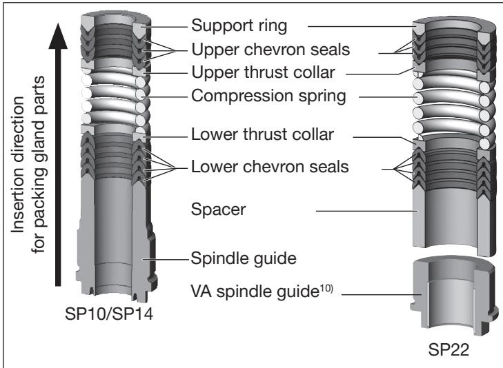
| Spindle Guide (10 mm stem) | DN 25 (SP10) | 6 Nm |
Mandatory Actuator Pressurization During Service
When removing or installing the actuator onto the valve body, or when turning the actuator orientation, the valve must be fully opened. For Control Function A, apply 5 bar(g) compressed air to pilot port 1. Attempting to rotate or torque the assembly while closed causes severe shear damage to the PTFE seat seal and seating contour.
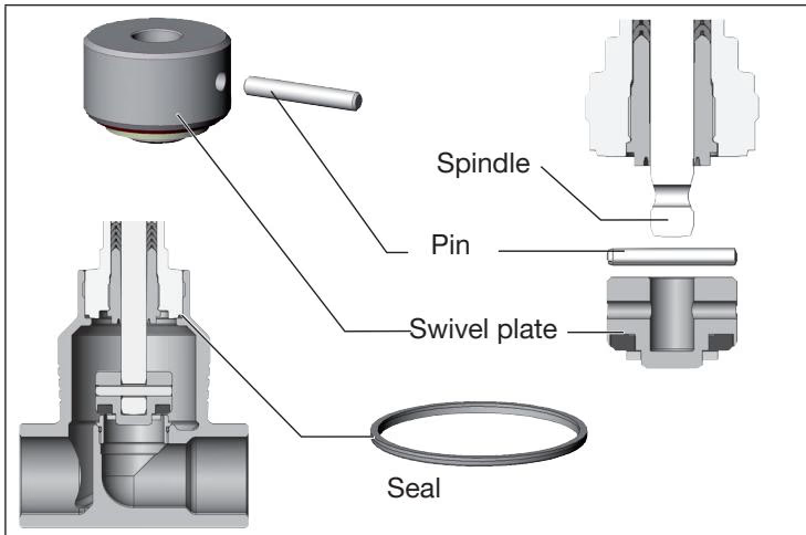
Under normal service conditions with clean, non-abrasive fluids, the PPS actuator is completely maintenance-free. Wearing components located in the flow stream (swivel plate, PTFE seal, body seals, and stem packing gland) can be replaced on-site without removing the valve body from the pipeline.
| Kit Description | Contents | Manufacturer Order No. |
|---|---|---|
| Valve Set DN 25 | Swivel plate with PTFE seal, grooved pin, body seal | 160 737 |
| Valve Seat Set DN 25 | Coated valve seat, body seal, lubricant | 262 170 |
| Standard Packing Gland Set | 7 chevron V-rings, thrust collars, spring, guide, seal, grease | 216 433 |
| Water Variant Packing Gland Set | High-cycle water configuration up to +200 °C | 372 661 |
| High-Temperature Packing Gland Set | Steam and thermal fluid configuration up to +230 °C | 372 662 |
| Valve Seat Assembly Socket Tool | Dedicated socket for DN 25 screwed-in valve seat | 652 606 |
| Modified Packing Gland Socket | 19 mm AF modified socket for Ø 10 mm spindle guide | 683 221 |
Stored Energy Hazard in Actuator
Never attempt to dismantle or unscrew the actuator casing. The internal actuator chamber houses a mechanical return spring under high mechanical pre-load. Opening the actuator casing will cause violent ejection of the spring, resulting in fatal or severe physical injury.
Hazardous Area Grounding Requirements
When installed in Zone 1/21 or 2/22 explosive gas and dust atmospheres under certification EPS 18 ATEX 2 008 X, the valve body must be grounded to the pipeline potential equalization system. Ground any isolated conductive components using the integrated grounding clip. To avoid dangerous electrostatic charges, wipe housing surfaces only with a damp or anti-static cloth.
Explore similar products in our catalog



