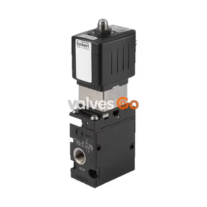
PN16

BURKERT 20014280 Type SVVI 11mm working module for Type 8650 valve islands. Features FM20 flange, D6 working port, and integrated check valves.
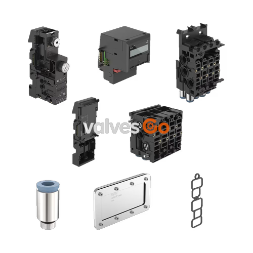
BURKERT 20014280 Type SVVI is an 11 mm working module designed for integration into Type 8650 valve islands. This revision 2 module features an FM20 flange, a D6 working port, and a valve interface designed for double valves (MK07). It is equipped with integrated check valves in ports 3 (R) and 5 (S), and supports pneumatic HotSwap functionality in port 1 (P). The module is intended for building modular electro-pneumatic valve blocks to control suitable pneumatic consumers in industrial automation systems.
Safety Instructions
Risk of injury from high pressure and escaping medium: Switch off the pressure and vent or empty the lines before working on the modules, device, or system. Electrostatically sensitive components (ESD): The modules contain electronic components susceptible to electrostatic discharge. Do not touch electronic components when the supply voltage is connected. Meet EN 61340-5-1 requirements to avoid damage.
The SVVI valve unit is composed of pneumatic and electronic base modules and valves, designed for use in a control cabinet or switch box (minimum IP54 degree of protection).
The pneumatic base module is a core component of the valve unit. It supports the valves, is used for the pneumatic supply and venting of the valves, and provides the pneumatic working outputs.
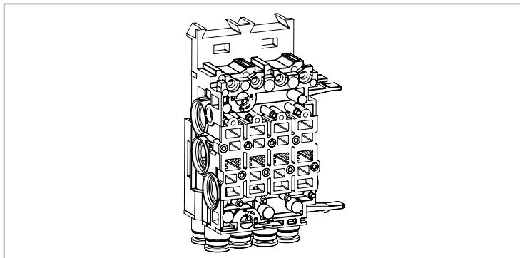
The electronic base module contains the electric plug connections for the valves and the electronics assembly for controlling the valves. It connects to neighboring modules via its electrical interface to receive power and control signals.
The following valves can be integrated into the valve units:
| Item | Valve type | Function |
|---|---|---|
| 1 | 6524 | 3/2-way valve |
| 2 | 6524 | 2x3/2-way valve |
| 3 | 6525 | 5/2-way valve |
| 4 | 0460 | 5/2-way pulse valve |
| without fig. | 0460 | 5/3-way valve |
| without fig. | 0498 | Unlockable double check valve |
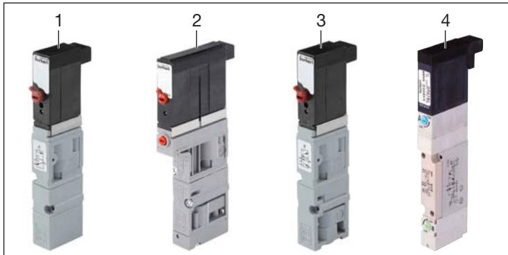
Optionally, the valves of types 6524 and 6525 can be equipped with a 2nd connection (pressed-on cable) for channel-by-channel safety-related shut-off.
When putting valve blocks together, a valve block consists—when viewed from left to right—of a "left connection module", one or more valve units, and a "right connection module". Central connection modules can be placed between valve units to guarantee mechanical fixation on the standard rail or sufficient supply of medium.
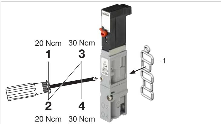
When reinstalling the valves on the valve unit, ensure that the flange seal (Item 1) is inserted correctly into the valve. Tighten the fastening screws of the valves crosswise, observing the required tightening torque.
Preparatory work:
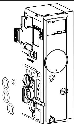
Installation steps:
Concluding work: Conduct a visual inspection to ensure the units fit parallel to each other with almost no gaps. Fasten the valve block to the standard rail by rotating the connection module fastening screws clockwise until they stop. Finally, conduct a pressure test by applying pressure to port P to check for tightness.
Explore similar products in our catalog