

PN16

BURKERT 20024803 (Type 8652) is a 24-slot AirLINE valve island with PROFIBUS DPV1, stainless steel AirLINE Quick plate, 48 digital inputs, and 24 dual 3/2-way NC solenoid valves for process automation.
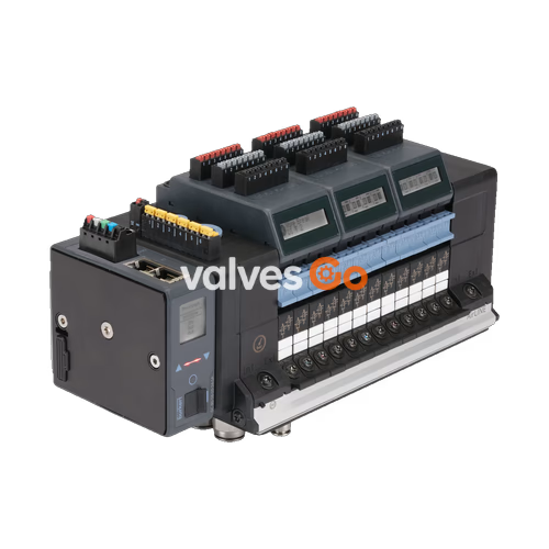
BURKERT 20024803 (Type 8652) is a 24-station AirLINE pneumatic valve island configured with a stainless steel AirLINE Quick adapter plate, PROFIBUS DPV1 communication interface, and 48 digital inputs distributed across 6 electronic display modules. All 24 valve slots are fully populated with dual 3/2-way normally closed solenoid valves (Circuit function C), providing 48 independently actuated pilot channels for process automation systems. The assembly is optimized for direct cabinet floor or wall mounting, routing compressed air connections directly through the panel boundary via push-in stainless steel fittings.

Article 20024803 represents an AirLINE 8652 24-bank ALQ VA assembly factory-configured with the following specific hardware and communication properties:
| Configuration Property | Factory Specification |
|---|---|
| Article Number | 20024803 |
| Base Model Family | Type 8652 AirLINE |
| Number of Valve Slots | 24 PCE |
| Valve Positions 1 to 24 | Dual 3/2-way normally closed, CF-C (2x 3/2-way CF-C per slot, 48 total valve channels) |
| Fieldbus Module Protocol | PROFIBUS DPV1 |
| Hardware Communication Interface | Sub-D 9-pin socket |
| Digital Input Equipping | 48 Digital Inputs (Modules 1 to 6 equipped with DI: Yes) |
| AirLINE Quick Plate Material | Stainless steel 1.4301 (ALQ VA) |
| Supply Port Connection Size | Push-in connector D10 mm |
| Working Port Connection Size | Push-in connector D6 mm |
| Pneumatic Port Materials | Stainless steel 1.4401 (working and supply ports) |
| Auxiliary Pilot Air Mode | Internal pilot air supply |
| Intermediate Air Feed | 1 PCE intermediate feed module included |
| Additional Supply Connections | Left: Push-in D6 and D10; Right: Without; Middle: Without |
| Integrated Check Valves (Ports 3/5) | No |
| Pneumatic HotSwap in Port 1 (P) | No |
| Protection Rating | IP20 standalone; IP65 mounted in enclosed cabinet |
Type 8652 operates with filtered compressed air according to ISO 8573-1:2010 Class 7.4.4. The manifold uses polyamide body construction with NBR and PUR seals.
| Technical Parameter | Specified Value |
|---|---|
| Manifold Body Material | PA (Polyamide) |
| Sealing Material | NBR and PUR |
| Station Width | 11 mm per valve slice |
| Maximum Controllable Valve Channels | Up to 48 functions |
| Operating Pressure Range | -1.0 bar to 10.0 bar (vacuum to 10 bar) |
| External Auxiliary Pilot Air Pressure | 3.0 bar to 10.0 bar |
| Nominal Flow Rate $Q_{\text{Nn}}$ (Air) | 310 l/min (at +20 °C, 6 bar inlet, 1 bar differential) |
| Flow Rate with HotSwap Option | Approx. 3% flow reduction |
| Operating Duty Cycle | 100% continuous operation (ED) |
| Operating Voltage | 24 V DC (±10% tolerance, 1 Vss maximum residual ripple) |
| Power Consumption per Valve | 0.7 W nominal (0.175 W after electronic power reduction) |
| Current Draw per Valve | 29 mA nominal (10 mA after power reduction) |
| Electrical Protection Class | Class III per DIN EN 61140, VDE 0140 |
| Operating Medium | Oil-free or lubricated dry compressed air, neutral gases (5 µm filtration recommended) |
| Compressed Air Quality Class | ISO 8573-1:2010 Class 7.4.4 |
| Ambient Operating Temperature | -10 °C to +55 °C |
| Storage Temperature | -20 °C to +60 °C |
| Mounting Orientation | Any |
Pilot Air Requirement
For standard internal pilot operation, the main supply line pressure must provide a minimum of 3.0 bar to maintain pilot valve operation.
The AirLINE Quick adapter plate integrates pneumatic bulkhead feedthroughs into the base of the valve island. This configuration mounts directly into a cutout in the cabinet floor or cabinet wall, eliminating individual panel-feedthrough fittings and internal tubing runs.
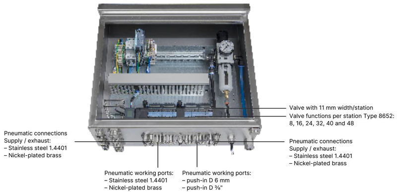
| Component Feature | Specification Details |
|---|---|
| Adapter Plate Material | Stainless steel 1.4301 (or anodized aluminum) |
| Pneumatic Port Materials | Stainless steel 1.4401 (or nickel-plated brass) |
| Available Station Capacities | 8, 16, 24, 32, 40, and 48 valve functions |
| Supply and Exhaust Ports (1, 3, 5) | Push-in connector D10 mm (or 3/8") |
| Working Ports (2, 4) | Push-in connector D6 mm (or 1/4") |
| Mounting Location | Control cabinet floor or control cabinet wall |
Cabinet Space Optimization
Mounting the valve island with the AirLINE Quick plate directly on the control cabinet floor significantly reduces cabinet volume and installation labor by allowing all pneumatic hoses to connect externally.
Article 20024803 is fully fitted with Circuit Function C across all 24 slots. Each slot contains two 3/2-way servo-controlled normally closed pilot valves based on Type 6534/6164 technology.
| Circuit Function Symbol | Function Description | Orifice Size | Nominal Flow $Q_{\text{Nn}}$ | Pressure Range | Response Time Open / Close |
|---|---|---|---|---|---|
| CF C (WW C): 2x 3/2-way | Dual 3/2-way solenoid valve, servo-controlled, normally closed, manual override | 4 mm | 270 l/min | Vac. to 10 bar (pilot 3 to 10 bar) | 15 ms / 15 ms |
Dimensions are stated in millimeters. Article 20024803 utilizes a 24-valve configuration with an intermediate supply module.
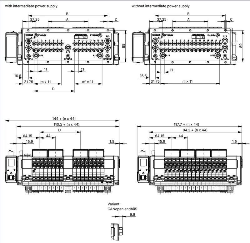
| Variant Configuration | Dimension A (mm) | Dimension B (mm) | Fastening C | Dimension D (mm) | m | m' | n |
|---|---|---|---|---|---|---|---|
| 16-fold with intermediate supply | 112 | 224 | 10 x M5 | 114.3 | 7 | 7 | 4 |
| 20-fold with intermediate supply | 134 | 268 | 10 x M5 | 158.3 | 11 | 7 | 5 |
| 24-fold with intermediate supply (20024803) | 156 | 312 | 10 x M5 | 158.3 | 11 | 11 | 6 |
| 16-fold without intermediate supply | 99 | 198 | 10 x M5 | — | 15 | — | 4 |
| 20-fold without intermediate supply | 121 | 242 | 10 x M5 | — | 19 | — | 5 |
| 24-fold without intermediate supply | 143 | 286 | 10 x M5 | — | 23 | — | 6 |
For 4-, 8-, and 12-fold variants without intermediate supply, mounting dimensions are:
Type 8652 separates the power supply for the electronic communication and displays from the coil drive circuit supplying the pneumatic valves.
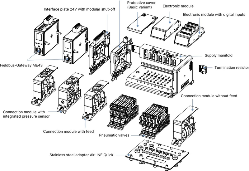
Power Isolation
Always feed the communication electronics (24 V DC) and the valve actuation coils (AUX 24 V DC) from dedicated lines to prevent inductive load switching interference from disturbing fieldbus communications.
Article 20024803 communicates over PROFIBUS DPV1 via a standard Sub-D 9-pin connector.
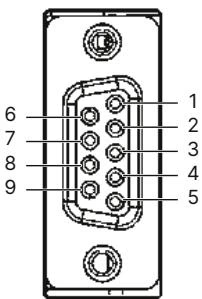
| Pin | PROFIBUS DPV1 Signal Assignment |
|---|---|
| 1 | Shielding / Protective Ground |
| 2 | M24 (optional) |
| 3 | RxD / TxD-P (B line) |
| 4 | CNTR-P (control signal, optional) |
| 5 | DGND (data ground) |
| 6 | +5 V (supply voltage for bus terminating resistor) |
| 7 | +24 V (optional) |
| 8 | RxD / TxD-N (A line) |
| 9 | CNTR-N (control signal, optional) |
Article 20024803 includes 6 display modules with integrated 8-channel digital inputs (48 DI channels total). Each input provides a 24 V sensor supply limited to 30 mA maximum per channel.
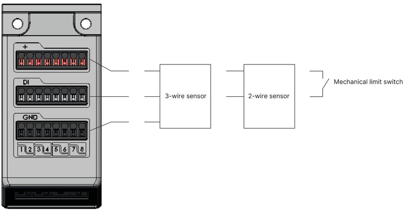
| Technical Parameter | Specification |
|---|---|
| Supported Sensor Types | 2-wire sensors, 3-wire sensors, mechanical potential-free switches |
| Switching Threshold | $V_{\text{OFF}} = 0\text{ to }5\text{ V}$, $V_{\text{ON}} = 10\text{ to }30\text{ V}$ |
| Input Current at $V_{\text{ON}}$ | Maximum 5.7 mA per channel (typical at 24 V DC) |
| Input Impedance | $> 4\text{ k}\Omega$ |
| Galvanic Isolation | No (all channels share common reference potential) |
| Permissible Wire Cross-Section | $0.14\text{ mm}^2\text{ to }1.5\text{ mm}^2$ (AWG 28 to 16) |
| Maximum Cable Length | $< 30\text{ m}$ |
| Monitored Condition | 3-Wire Sensor | 2-Wire Sensor | Mechanical Limit Switch |
|---|---|---|---|
| Sensor Actuated | Supported | Supported | Supported |
| Sensor Not Actuated | Supported | Supported | Supported |
| Short Circuit Detection | Supported | Not supported | Not supported |
| Wire Break Detection | Not supported | Supported | Not supported |
Individual spare parts, gateway modules, and software configuration tools available for Type 8652 include:
When installed in an appropriate enclosure, Type 8652 configurations carry global approvals for industrial and hazardous areas:
Hazardous Area Operating Conditions
In explosive atmospheres, electrical terminal blocks (24 V, SIA, EVS, and DI) must never be plugged or disconnected while energized. Hot swapping of pneumatic valves is prohibited unless the absence of an explosive atmosphere has been verified using approved testing apparatus.
Explore similar products in our catalog


