


Up to 99.8% Efficiency

BURKERT 20032010 (Type 3361) electromotive globe control valve features AG2 1300 N linear actuator, DN 10 DIN EN 1092-1 PN25 flange, stainless steel CF3M body, display module, and 24 V DC analogue control.
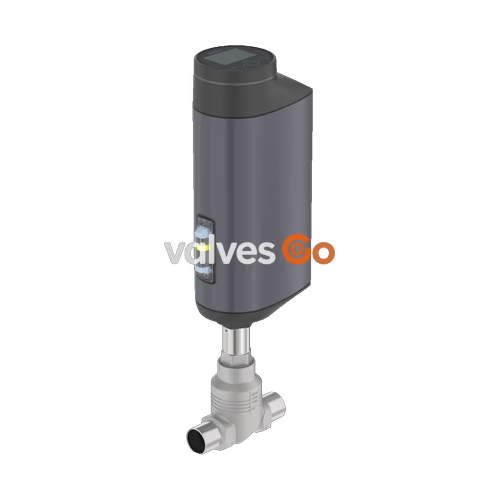
BURKERT 20032010 (Type 3361) is an electromotive 2-way globe control valve engineered for precision continuous control of neutral and aggressive liquids, steam, and gases in industrial processes. The unit combines an AG2 brushless electromotive linear actuator delivering 1,300 N positioning force with a DN 10 DIN EN 1092-1 PN25 flanged body in cast stainless steel CF3M. Featuring a ball-screw drive with a linear travel speed of 6 mm/s and a dead band of ±0.1%, this configuration provides rapid response to control signals with a typical full-stroke closing time of 3.4 seconds. Process pressure variations do not transfer back to the valve stem position. The screwed-in valve seat has a 10 mm orifice, delivering a nominal Kv value of 2.7 m³/h (Cv 3.1 gpm) with an equal-percentage 50:1 characteristic and Class IV metal-to-metal shut-off tightness.
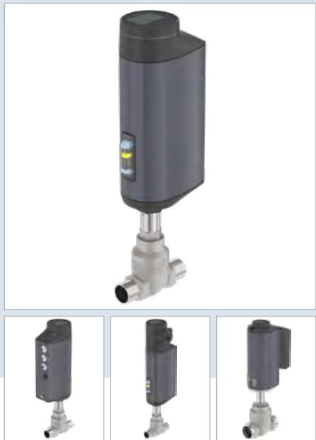
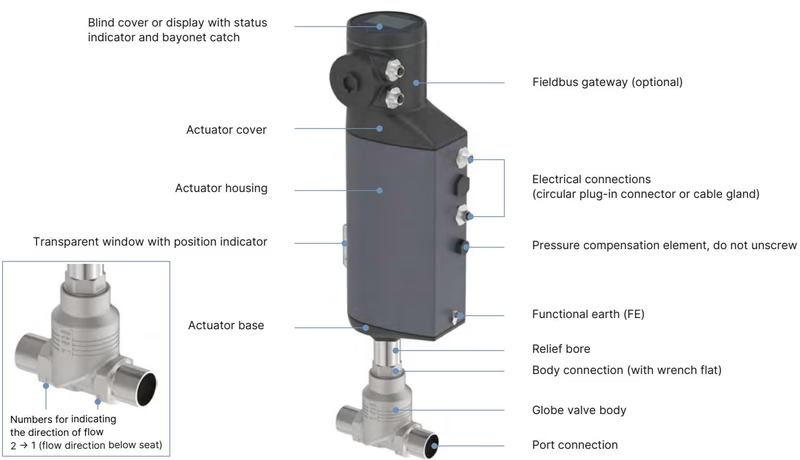
This specific article includes a digital display module with operating keys, 360° LED status light ring, mechanical position indicator, and an analogue control interface with büS service communication. Flow direction is configured below the seat (2 to 1), preventing water hammer during liquid flow regulation. Without an energy storage pack, the actuator securely blocks and holds position upon total power failure.
| Parameter | Specification |
|---|---|
| Product Identification | Article no. 20032010, Type 3361 |
| Valve Design | 2-way globe control valve, straight-seat body |
| Port Connection Size | DN 10 (NPS 3/8) |
| Flange Standard | DIN EN 1092-1 PN 25 (Face-to-face FTF 1 per DIN EN 558-1) |
| Pressure Rating | PN 25 (DIN EN 1333), Class 150 (DIN EN 1759) |
| Operating Pressure Range | 0 to 25 bar(g) |
| Actuator Size & Driving Force | AG2 (actuator size 2, 1,300 N nominal force) |
| Actuator Drive Principle | Brushless DC motor with precision gear and ball screw |
| Linear Travel Speed | 6 mm/s (for 1,300 N actuator force) |
| Typical Closing Time | 3.4 s (3,400 ms) |
| Position Control Dead Band | ± 0.1% |
| Flow Direction | Below seat (against closing direction, port 2 → port 1) |
| Orifice / Seat Size | 10 mm (3/8") |
| Kv Value (Water) | 2.7 m³/h (measured per DIN EN 60534-2-4) |
| Cv Value | 3.1 gpm |
| Flow Characteristic | Equal percentage (theoretical rangeability 50:1) |
| Seat Leakage Class | Class IV (DIN EN 60534-4) |
| Operating Voltage | 24 V DC ± 10% (residual ripple max. 10%) |
| Current Consumption | Max. 3 A at maximum load (standby consumption 2 to 5 W) |
| Duty Cycle | 100% continuous |
| Protection Class (DIN EN 61140) | III |
| Power Failure Safety Setting | Blocked in last position (no energy storage pack fitted) |
| Medium Temperature Range | -10 °C to +150 °C |
| Ambient Temperature Range | -25 °C to +55 °C |
| Dynamic Viscosity Limit | Up to 600 mm²/s |
| Maximum Weight (Actuator) | Approx. 5.5 kg |
| Ingress Protection | IP65 / IP67 (DIN EN 60529), NEMA 4X |
BURKERT 20032010 conforms to relevant European directives and holds international hazardous location and sanitary ratings:
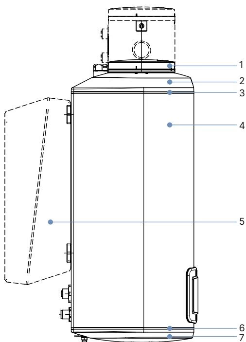
| Item | Component | Material |
|---|---|---|
| 1 | Display housing / blind cover | PPS (standard) / Stainless steel 1.4301 (ATEX/IECEx variants) |
| 2 | Actuator cover | PPS |
| 3 | Seal | EPDM |
| 4 | Actuator housing | Powder-coated aluminium |
| 6 | Seal | EPDM |
| 7 | Actuator base | PPS |
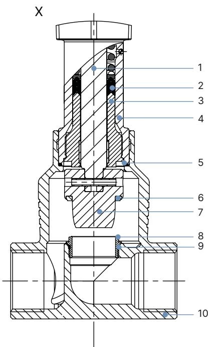
| Item | Component | Material |
|---|---|---|
| 1 | Spindle (stem) | Stainless steel 1.4401 (316) / 1.4404 (316L) |
| 2 | Spindle seal | PTFE V-rings (filled) with spring compensation |
| 3 | Spindle guide | Stainless steel 1.4404 (316L) |
| 4 | Packing gland tube | Stainless steel 1.4401 (316) |
| 5 | Body seal | Graphite or PTFE |
| 6 | Seat seal | Stainless steel 1.4571 (metal-to-metal contact) |
| 7 | Control cone | Stainless steel 1.4571 |
| 8 | Valve seat | Stainless steel 1.4571 (screwed-in replaceable design) |
| 9 | O-ring (valve seat) | EPDM or PTFE |
| 10 | Valve body | Stainless steel CF3M (1.4409 / 316L cast equivalent) |
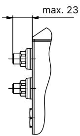
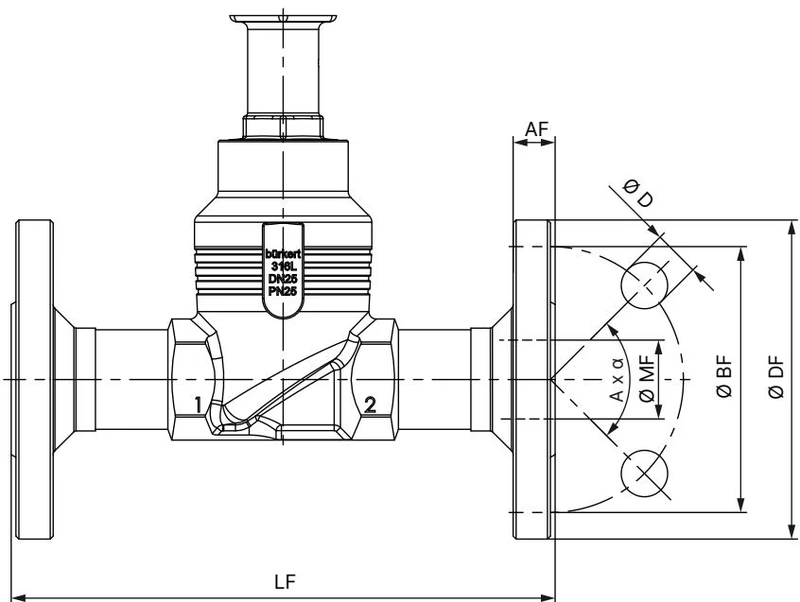
| Nominal Diameter DN | NPS | Height H1 (Standard Variant) [mm] | Height H2 (Fieldbus Variant) [mm] |
|---|---|---|---|
| 10 | 3/8 | 417 | 489 |
| 15 | 1/2 | 417 | 489 |
| 20 | 3/4 | 423 | 495 |
| 25 | 1 | 446 | 518 |
| 32 | 1 1/4 | 474 | 546 |
| 40 | 1 1/2 | 479 | 551 |
| 50 | 2 | 485 | 557 |
Note on height dimensions: Dimensions exclude the closed sealing function. In the closed position, the actuator raises by approximately 2 mm.
| Parameter | Value (DN 10) |
|---|---|
| Flange Outer Diameter (∅ DF) | 90 mm |
| Face-to-Face Length (LF) | 130 mm |
| Bolt Circle Diameter (∅ BF) | 60 mm |
| Flange Thickness (AF) | 16 mm |
| Bolt Hole Diameter (∅ D) | 14 mm |
| Number of Bolt Holes & Orientation (A × α) | 4 × 90° |
| Raised Face / Internal Orifice Diameter (∅ MF) | 13.6 mm |
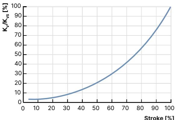
BURKERT 20032010 provides an equal-percentage flow characteristic compliant with DIN EN 60534-2-4 with a theoretical rangeability of 50:1. The relationship between stroke percentage and flow coefficient Kv (measured with water at +25 °C) for DN 10 with seat size 10 is structured below:
| Stroke (%) | Kv Value [m³/h] |
|---|---|
| 10% | 0.11 |
| 20% | 0.13 |
| 30% | 0.19 |
| 40% | 0.30 |
| 50% | 0.48 |
| 60% | 0.73 |
| 70% | 1.00 |
| 80% | 1.60 |
| 90% | 2.30 |
| 100% (Kvs) | 2.70 |
Operating Limits for Seat Seal
Metallic stainless steel seat seals provide tight process performance across -40 °C to +230 °C. Because metallic seals permit permissible leakage rates of 0.01% of nominal flow under Class IV (DIN EN 60534-4), an upstream or downstream shut-off valve is recommended when absolute drop-tight shut-off (Class VI) is demanded.
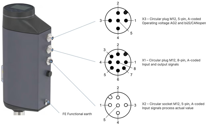
Article 20032010 operates on a 24 V DC power supply via M12 circular connectors. Two multipole connectors are positioned on the actuator base for standard analogue configuration:
| Pin | Signal Assignment |
|---|---|
| 1 | Digital input + |
| 2 | GND for digital input and digital outputs |
| 3 | Digital output 2 + |
| 4 | Digital output 1 + |
| 5 | Analogue output - |
| 6 | Analogue output + |
| 7 | Set-point value / Analogue input - |
| 8 | Set-point value / Analogue input + |
| Pin | Signal Assignment |
|---|---|
| 1 | CAN Shield / shield |
| 2 | Operating voltage 24 V DC ± 10% |
| 3 | GND / CAN_GND |
| 4 | CAN_H |
| 5 | CAN_L |
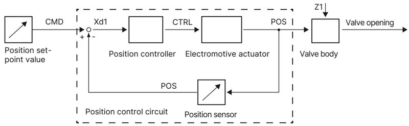
The electromotive linear actuator consists of a brushless DC motor, planetary gear, and precision ball-screw spindle mechanism. The position sensor continuously detects actual spindle position (POS), which the internal positioner compares against setpoint value (CMD). Any control deviation (Xd1) triggers the actuating variable (CTRL) to reposition the drive without overshoot.
Mechanical Override Limit
Actuate the mechanical manual override only when the supply voltage is completely disconnected. Applying an operating torque exceeding 2 Nm when reaching valve end positions damages the mechanical override mechanism.
Installation is permitted in any mounting orientation, with the upright vertical position recommended. Piping must be cleaned and de-pressurized before installation.
| Joint / Component | Size / Tool | Tightening Torque |
|---|---|---|
| Valve body to actuator connection | DN 10 / Open-end wrench | 45 ± 3 Nm (33 ± 2 lbf·ft) |
| Valve seat installation | Seat size 10 (DN 10) / Installation tool | 20 + 3 Nm |
| Spindle guide (lower) | ø10 mm spindle / Modified socket SW19 | 15 Nm |
| Actuator base screws (4x) | Hexalobular internal T25 | 5 Nm |
| Display module fastening screw | Hexalobular internal T20 | 1.1 Nm |
Calibration via X.TUNE
Never initiate the X.TUNE self-calibration function under medium pressure. Pressurizing the valve during calibration leads to incorrect controller end-position detection and uncontrolled process errors.
To execute X.TUNE on units with a display module, verify line pressure is fully vented, navigate to CONFIGURATION → Position Controller → MAINTENANCE → CALIBRATION → X.TUNE, select the stainless steel seat seal material, and confirm calibration execution.
Explore similar products in our catalog


