

PN16

BURKERT 20039114 Type 8647 AirLINE SP is a 28-bank REV2 pneumatic valve island for Siemens ET 200SP/SP HA, featuring 11 mm stations, G 1/4 ports, D6 push-in connections, P-shutoff HotSwap, and IP20 DIN-rail mounting.
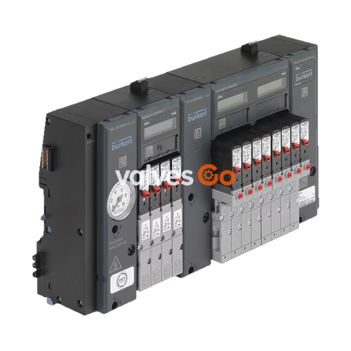
BURKERT 20039114 (Type 8647) AirLINE SP is a modular electropneumatic automation system configured as a 28-bank pneumatic valve island in revision 2 (REV2). Developed for direct mechanical and electrical docking to Siemens SIMATIC ET 200SP and SIMATIC ET 200SP HA distributed I/O systems, the unit enables centralized pilot control of pneumatic actuators, process valves, and cylinders directly within the automation rack. The island features an 11 mm station pitch, mixed 3/2-way pilot valve configuration, G 1/4 primary air supply connections, one intermediate feed module (PSU-M), bottom-oriented D6 push-in working ports, integrated non-return check valves on exhaust channels 3 (R) and 5 (S), and pneumatic HotSwap check valves on supply channel 1 (P).
Operating across a nominal pressure span of 2.5 to 10.0 bar, the valve island provides continuous duty (100% ED) pneumatic switching for medium temperatures between 0 °C and +50 °C and ambient cabinet temperatures between 0 °C and +55 °C. Electrical power and fieldbus communication are established automatically through the backplane bus of the adjoining Siemens ET 200SP BaseUnits. Channel diagnostics, valve switching cycles, and visual status indication are rendered on localized module liquid crystal displays and light-emitting diodes, conforming to IP20 enclosure standards on standard DIN rail mountings.
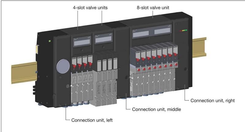
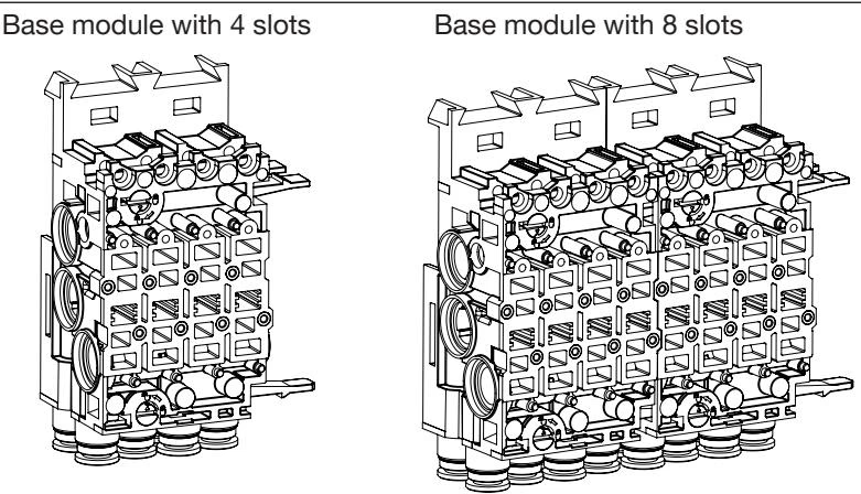
BURKERT Type 8647 REV2 introduces optimized pneumatic base modules, connection units, and valve interfaces. The mechanical and fluidic interface between the single valves and the pneumatic base module is standardized using the FM20 pattern across single 3/2-way, single 5/2-way, and double 2x3/2-way pilot valves.
| Distinguishing Feature | Generation REV1 | Generation REV2 (Model 20039114) |
|---|---|---|
| Push-in release ring color | Black | Blue |
| Working port channel alignment | Parallel | Wavy (offset staggered) |
| Type label designation | Without "Rev." marking | Marked explicitly with "Rev.2" |
| Flange pattern for single valves | FM14 pattern | Standardized FM20 pattern |
| Flow reduction with integrated P-shutoff | Up to 50% reduction | Reduced by approximately 20% |
Flange Profile Incompatibility
Single valves Type 6524 (3/2-way) and Type 6525 (5/2-way) from generation REV1 cannot be mounted on REV2 pneumatic base modules. The mechanical guide profiles prevent cross-mounting. When servicing or replacing valves on article 20039114, only REV2-designated replacement valves with FM20 flange patterns must be used.
Type 8647 integrates directly into Siemens automation topologies without requiring point-to-point discrete wiring between PLC output cards and solenoid coils. The valve island communicates through the interface module (IM 155-6 PN or IM 155-6 DP) or ET 200SP CPU via the internal backplane bus.
| Engineering Characteristic | SIMATIC ET 200SP Integration | SIMATIC ET 200SP HA Integration |
|---|---|---|
| PROFINET IO (GSDML) support | Yes | Yes |
| PROFIBUS DP (GSD) support | Yes | No |
| TIA Portal HSP integration | Yes (HSP0225) | No |
| STEP 7 Classic HSP integration | Yes (HSP2105) | No |
| PCS 7 HUP integration | Yes (HF interface module required) | Yes (PCS 7 V9.0 SP2 or higher) |
| Multiple valve blocks per station | Yes (requires new potential feeder) | No (maximum 1 valve block per station) |
| Maximum permissible station width | 975 mm (excluding interface module) | 1240 mm (excluding interface module) |
| Additional I/O modules to the right | Permitted | Not permitted |
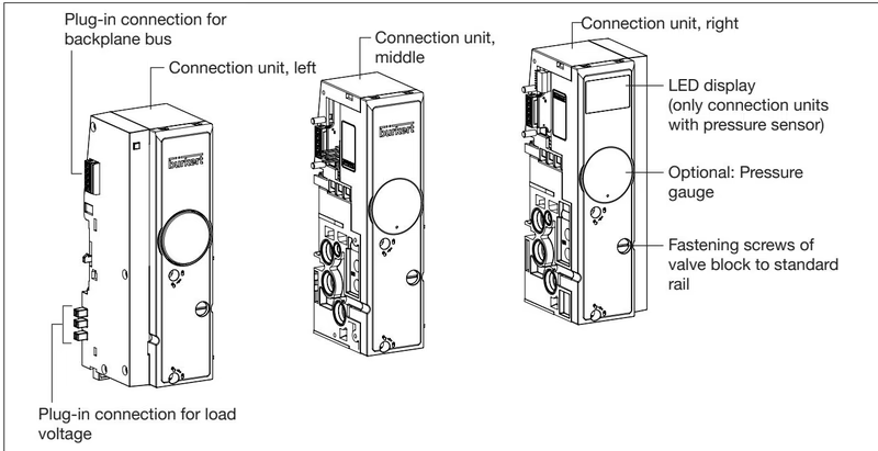
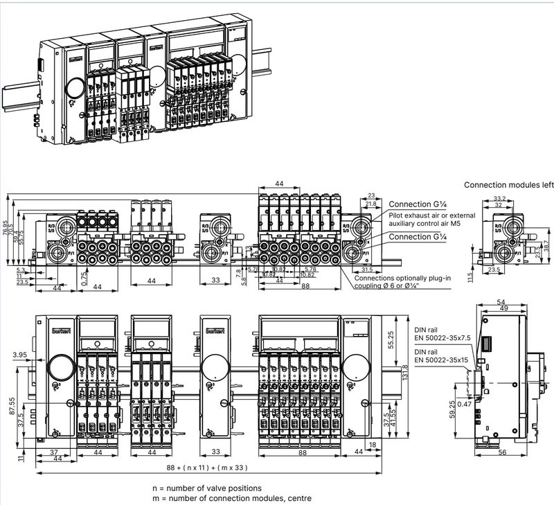
Article 20039114 incorporates 28 valve stations organized along an 11 mm pitch grid. The assembly is bounded by connection units that distribute supply pressure and collect exhaust flow.
Intermediate Feed Requirement
Pneumatic supply guidelines dictate that an intermediate supply unit (PSU-M) is required after every 24 valve functions (or after 16 valve functions when using 2x3/2-way double valves). Article 20039114 includes one factory-configured intermediate feed unit (PSU-M, G 1/4) to maintain uniform line pressure across all 28 valve stations.
| Port Thread / Size | Function / Designation | Recommended Tightening Torque | Maximum Tightening Torque |
|---|---|---|---|
| G 1/4 | Supply port 1 (P), Exhaust ports 3 (R) and 5 (S) | 4.0 to 7.0 Nm | 20.0 Nm |
| M5 | Auxiliary control air / pilot exhaust (X) | 1.0 to 1.2 Nm | 3.0 Nm |
| M7 | AirLINE Quick push-in connector sleeve | 1.75 to 2.25 Nm | 4.0 Nm |
The 28 valve slots are populated with high-speed solenoid pilot valves mounted onto 4-slot or 8-slot pneumatic and electronic base units.
| Valve Model | Circuit Function | Orifice | Nominal Flow ($Q_{\text{Nn}}$) | Pressure Range | Opening Time | Closing Time | Coil Power |
|---|---|---|---|---|---|---|---|
| Type 6524 Single | 3/2-way NC (Circuit C) | 4.0 mm | 300 l/min | 2.5 to 10 bar | 15 ms | 28 ms | 0.8 W |
| Type 6524 Single | 3/2-way NO (Circuit D) | 4.0 mm | 300 l/min | 2.5 to 10 bar | 15 ms | 28 ms | 0.8 W |
| Type 6525 Single | 5/2-way (Circuit H) | 4.0 mm | 300 l/min | 2.5 to 10 bar | 20 ms | 28 ms | 0.8 W |
| Type 6524 Double | 2x3/2-way NC (Circuit C) | 4.0 mm | 300 l/min | 2.5 to 10 bar | 12 ms | 20 ms | 2 x 0.8 W |
| Type 0460 | 5/3-way locked (Circuit L) | 2.5 mm | 200 l/min | 2.0 to 7.0 bar | 15 ms | 20 ms | 1.0 W |
The electronic base modules house valve driver electronics, short-circuit and open-circuit wire break detection circuits, and front-facing LCD screens. Each channel features two independent switching cycle counters: one tracking pilot valve operations and one tracking field actuator cycles. Acyclic communication records maintenance limits via control data records (DS130 to DS135).
Type 8647 supports three methods for de-energizing pilot valves during emergency or interlock conditions:
Article 20039114 incorporates automatic P-shutoff valves inside the pneumatic sub-base stations. Solenoid valves can be replaced under active line pressure without venting the entire manifold:
Push-In Pneumatic Tubing Guidelines
Pneumatic push-in connections conform to DIN ISO 14743:2020. To ensure leak-free operation and adequate tubing retention, hoses must be cut strictly perpendicular to their axis. Outer diameter tolerances must not exceed ±0.08 mm for 6 mm polyamide (PA) or ±0.10 mm for 6 mm polyurethane (PU). The minimum retention pull-out force is 120 N for PA tubing and 100 N for PU tubing.
| Specification Parameter | Value / Characteristic |
|---|---|
| Product Type | Type 8647 AirLINE SP Electropneumatic Valve Island |
| Manufacturing Article Number | 20039114 |
| Hardware Generation | Revision 2 (REV2) |
| Manifold Capacity | 28 valve slots (11 mm pitch) |
| Pilot Valve Configuration | Mixed population (predominantly 3/2-way functions) |
| Fluidic Connections | Supply: G 1/4; Exhaust: G 1/4; Working ports: D6 push-in (bottom) |
| Intermediate Air Feed | 1 intermediate unit (PSU-M, G 1/4) installed |
| Operating Pressure Range | 2.5 to 10.0 bar (relative pressure) |
| Operating Medium | Dry, neutral gases or compressed air (ISO 8573-1:2010 7.4.4, 5 µm filtered) |
| Flow Rate per Station ($Q_{\text{Nn}}$) | 300 l/min (reduced ~20% during active P-shutoff HotSwap) |
| Integrated Check Valves | Factory-fitted on ports 3 (R) and 5 (S) |
| Pneumatic HotSwap Function | Factory-fitted on port 1 (P) |
| Nominal Operating Voltage | 24 V DC (±10%, max. 2.4 Vss ripple) SELV/PELV |
| Maximum Load Current | Up to 3.0 A depending on concurrent coil firing |
| Ingress Protection Class | IP20 (verified according to EN 60529); IP65 in closed IP54+ cabinet |
| Ambient Operating Temperature | 0 °C to +55 °C |
| Medium Operating Temperature | 0 °C to +50 °C |
| Mounting Specification | Standard rail DIN EN 60715 with functional earth (FE) |
Explore similar products in our catalog


