


PN25

Bürkert 20051147 (Type 2101) is a normally open (CFB) pneumatic 2/2-way stainless steel globe valve, DN 40, rated 0–25 bar and -10 to +185 °C, featuring welded ends and PTFE seat sealing.
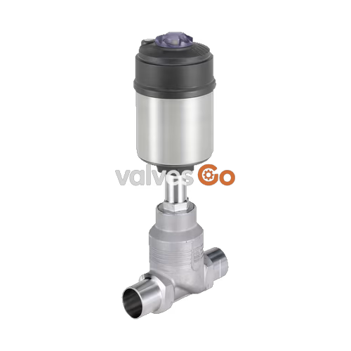
Bürkert 20051147 is a Type 2101 pneumatically operated 2/2-way globe valve configured with a DN 40 orifice, 316L stainless steel body, and welded pipe ends conforming to ISO 4200, DIN 11866 Series B, and DIN EN ISO 1127. The line connection dimensions feature an outer diameter of 48.3 mm, an inner diameter of 44.3 mm, and a pipe wall thickness of 2.0 mm. Configured under control function B (normally open, CFB), the valve remains open in its unpressurized rest position via internal spring action and closes against the flow direction through pilot pressure applied to the actuator.
Operating across process pressures from 0 to 25 bar (PN 25, Class 150) and media temperatures between -10 °C and +185 °C, the unit delivers a nominal water flow coefficient (Kv) of 31 m³/h. The valve utilizes a screwed-in seat, a stainless steel swivel plate with PTFE seat sealing, and a polyphenylene sulphide (PPS) piston actuator. Certified compliant with Regulation (EC) 1935/2004 for food contact and suited for CIP and SIP processes, the valve handles neutral gases, steam, water, alcohols, fuels, hydraulic fluids, saline solutions, lyes, and organic solvents.
Type 2101 valves consist of a pneumatically operated piston actuator coupled to a 2-way straight-seat body. A spindle connected to the internal actuator piston transmits opening and closing forces directly to the swivel plate assembly.
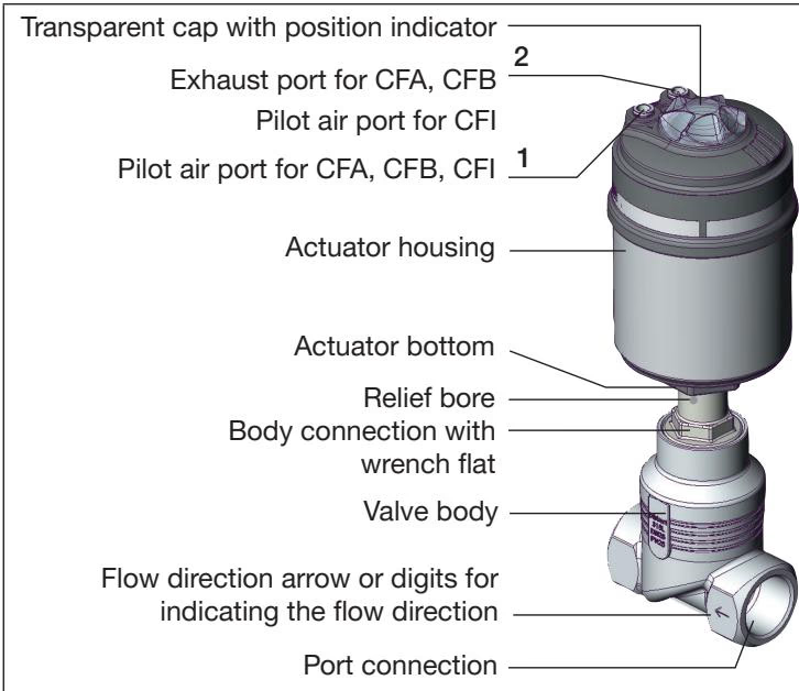
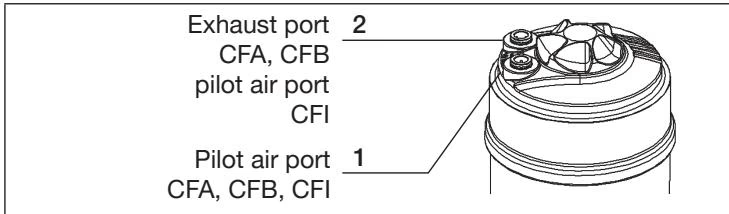
Under control function B (CFB), the valve is held open in the resting position by spring force. Applying pilot air pressure to pilot port 1 forces the actuator piston downward to seal the swivel plate against the screwed-in valve seat.

The medium enters below the valve seat. Because the operating pressure acts beneath the swivel plate, process pressure aids valve opening and eliminates the pressure hammer risk inherent to flow-above-seat configurations on liquid lines.
Minimum Pilot Pressure and Leak Tightness
Insufficient pilot air pressure or operating pressures exceeding the permitted 25 bar limit can cause seat leakage under control function B. Always maintain pilot pressure within the specified 2.5 to 7.0 bar range.
The maximum permitted operating pressure depends on the medium temperature according to the applicable pipeline standard.
| Temperature Range | Operating Pressure DIN EN 12516-1 (PN25) | Operating Pressure ASME B16.5 / B16.34 Cl. 150 | Operating Pressure JIS B 2220 10K |
|---|---|---|---|
| -10 °C to +50 °C | 25.0 bar | 18.4 bar (at 50 °C) / 19.0 bar (-29 to 38 °C) | 14.0 bar |
| +100 °C | 24.5 bar | 16.2 bar | 14.0 bar |
| +150 °C | 22.4 bar | 14.8 bar | 13.4 bar |
| +200 °C | 20.3 bar | 13.7 bar | 12.4 bar |
| +230 °C | 19.0 bar | 12.7 bar | 11.7 bar |
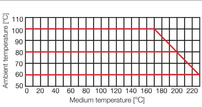
Ambient Temperature Limits
Push-in pilot air connectors allow ambient operating temperatures between -10 °C and +60 °C. When combining the valve with electrical pilot valves or control tops, the maximum ambient temperature is limited to +55 °C.
The valve may be installed in any physical orientation, preferably with the actuator oriented vertically upward. Ensure piping is accurately aligned and free of mechanical tension and debris before mounting.
When installing valves with welded ends, the actuator assembly must be detached from the valve body before welding into the pipeline to prevent thermal damage to the internal seals and actuator casing.
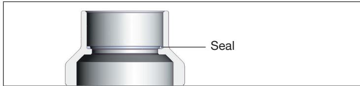
| Valve Body Connection Size | Body Tightening Torque |
|---|---|
| DN 15 | 45 ± 3 Nm |
| DN 20 | 50 ± 3 Nm |
| DN 25 | 60 ± 3 Nm |
| DN 32 | 65 ± 3 Nm |
| DN 40 (Bürkert 20051147) | 65 ± 3 Nm |
| DN 50 | 70 ± 3 Nm |
| DN 65 | 100 ± 3 Nm |
| DN 80 | 120 ± 5 Nm |
| DN 100 | 150 ± 5 Nm |
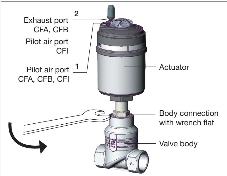
The actuator housing can be rotated 360° to optimize pilot air hose routing.
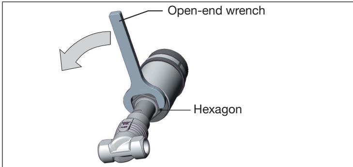
Rotation Direction
When turning the actuator, the valve must be in the open position. Rotate the actuator exclusively counterclockwise (as viewed from below). Turning clockwise risks loosening the body connection, leading to medium discharge under pressure.
Pilot air hoses measuring 6/4 mm or 1/4" connect directly into the push-in fitting at pilot port 1.
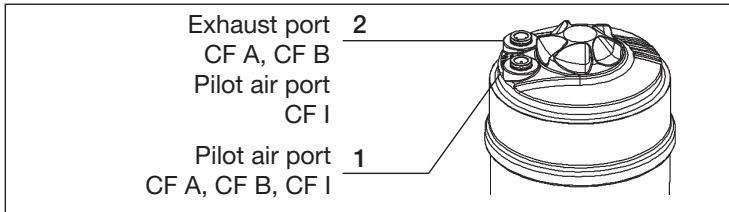
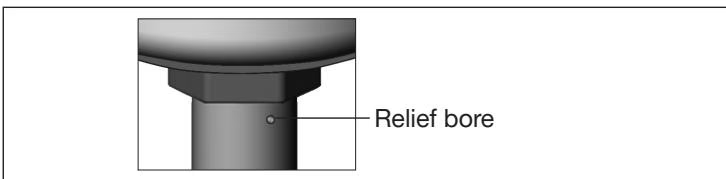
During ongoing operations, inspect the relief bore on the lower actuator neck regularly. Escaping process medium indicates wear of the spindle packing gland.
Under standard industrial conditions, the actuator mechanism is maintenance-free. Natural wear is restricted to the PTFE swivel plate, the valve seat, and the spindle packing gland chevron rings.
Residual Pressure and Stored Spring Force
Before opening lines or disassembling the valve, depressurize the pipeline, drain all process media, and vent the pneumatic supply. Do not attempt to open the actuator housing; internal springs are under mechanical tension.
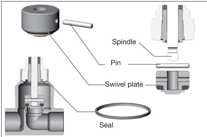
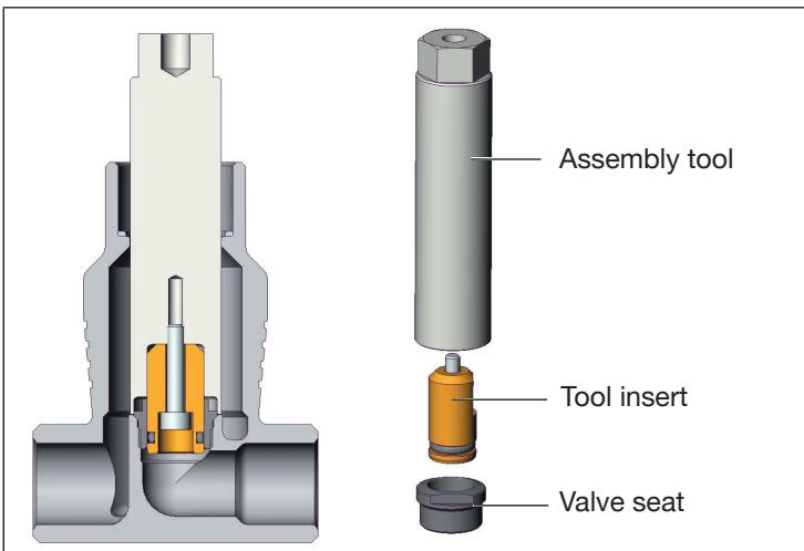
| Valve Seat Orifice Size | Coated Valve Seat Tightening Torque |
|---|---|
| DN 15 | 20 ± 3 Nm |
| DN 20 | 28 ± 3 Nm |
| DN 25 | 40 ± 5 Nm |
| DN 32 | 65 ± 5 Nm |
| DN 40 (Bürkert 20051147) | 85 ± 8 Nm |
| DN 50 | 120 ± 8 Nm |
| DN 65 | 150 + 10 Nm |
| DN 80 | 180 + 10 Nm |
| DN 100 | 220 + 10 Nm |
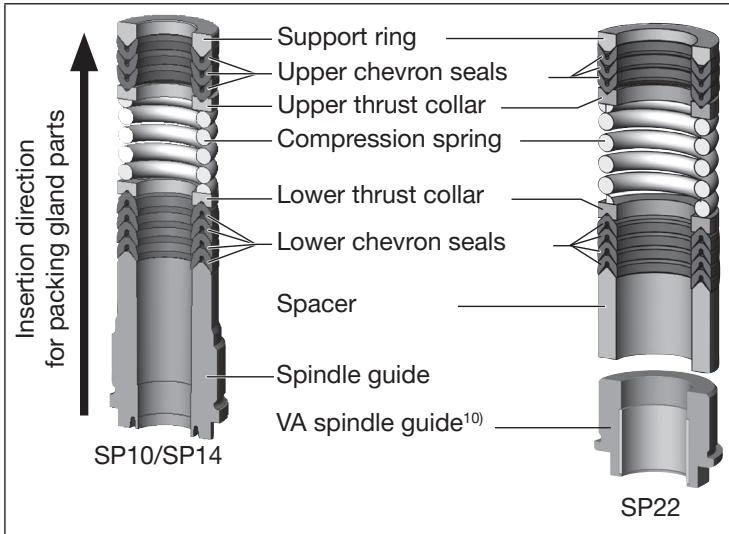
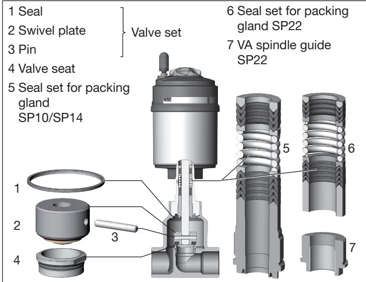
| Spare Part Set | Covered Size / Type | Order Number |
|---|---|---|
| Valve set (swivel plate with PTFE seal, pin, seal) | DN 40 | 011 209 |
| Valve seat set (seat, O-ring, seal) | DN 40 | 262 177 |
| Valve seat assembly tool | DN 40 | 652 608 |
| Packing gland seal set (Standard variant) | DN 15–50 (actuator ø 50 / ø 70 mm) | 216 433 |
| Packing gland seal set (Water outlet up to 200 °C) | DN 15–50 (actuator ø 50 / ø 70 mm) | 372 661 |
| Packing gland seal set (High-temperature up to 230 °C) | DN 15–50 (actuator ø 50 / ø 70 mm) | 372 662 |
| Modified socket wrench for packing gland | Spindle ø 10 mm (AF 19) | 683 221 |
| Modified socket wrench for packing gland | Spindle ø 14 mm (AF 21) | 683 223 |
| Fault | Cause | Action |
|---|---|---|
| Actuator does not switch | Pilot air connections interchanged | For CFB, ensure pilot pressure is connected to port 1. |
| Pilot pressure below 2.5 bar | Increase pilot pressure within 2.5 to 7.0 bar. | |
| Operating pressure above 25 bar | Verify system pressure conforms to type label. | |
| Medium flow direction inverted | Ensure arrow on body points in flow direction (below seat). | |
| Valve seat leaks | Debris between seal and seat | Clean valve interior; install upstream strainer. |
| PTFE seat seal worn or damaged | Install new swivel plate or valve set. | |
| Operating pressure too high | Reduce operating pressure below maximum limit. | |
| Pilot air pressure insufficient | Check pilot air supply and regulator. | |
| Leakage at actuator relief bore | Spindle packing gland worn | Replace packing gland seal set. |
Explore similar products in our catalog



