


PN25

BURKERT 20061740 (Type 2000) is a pneumatically operated 2/2-way angle seat valve featuring a DN25 weld end connection, 50 mm PA actuator, normally closed function, PTFE seal, and 14 m³/h flow capacity.
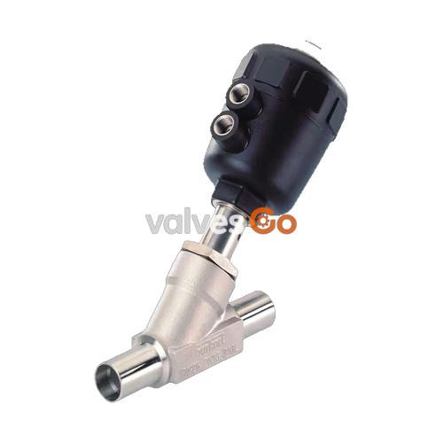
BURKERT 20061740 is a pneumatically operated 2/2-way angle seat valve from the CLASSIC Type 2000 family, designed for high-cycle on/off control of neutral gases, steam, water, alcohols, fuels, hydraulic fluids, and chemical solutions. This specific configuration features a DN25 (1", 25 mm orifice) flow path with pipe weld spigots measuring 29.0 × 1.5 mm in accordance with DIN 11850 series 2, DIN 11866 series A, and DIN EN 10357 series A. It is driven by a 50 mm diameter (size D) polyamide (PA) piston actuator featuring a stainless steel threaded bushing at the G 1/4 pilot port and an internal return spring fabricated from 1.4310 stainless steel.
Configured in Control Function A (normally closed by spring force), the valve directs flow beneath the seat (flow-to-open). This flow configuration eliminates water hammer in liquid systems when the valve closes against the process line. Burkert 20061740 achieves a flow coefficient (Kv) of 14 m³/h at a water test pressure drop of 1 bar. It operates against media pressures up to 5.2 bar(g) with a minimum pilot supply pressure of 4.1 bar(g) (maximum 10 bar(g)), across an operational process temperature envelope of -10 °C to +185 °C and an ambient range of -10 °C to +40 °C (capable of reaching +60 °C with media temperature derating).
Type 2000 valves combine an investment cast stainless steel body with an impact-resistant polymer actuator. Spindle sealing is maintained by a self-adjusting PTFE V-ring gland preloaded by an internal spring pack, minimizing fugitive emissions and eliminating manual packing adjustments.
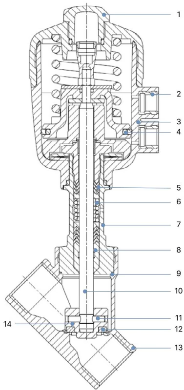
| Item No. | Component | Material Specification (Article 20061740) |
|---|---|---|
| 1 | Transparent Cover / Position Indicator | Polycarbonate (PC) |
| 2 | Pilot Air Port Bushing | Stainless steel 1.4305 (G 1/4) |
| 3 | Actuator Housing | Polyamide (PA, size 50 mm / Code D) |
| 4 | Piston Seal | Nitrile butadiene rubber (NBR) |
| 5 | Spindle Packing Gland | PTFE V-rings (filled), with spring compensation |
| 6 | Return Spring | Stainless steel 1.4310 |
| 7 | Guiding Tube | Stainless steel CF3M |
| 8 | Wiper Seal | PTFE (filled) |
| 9 | Body Seal | Graphite (PTFE optional) |
| 10 | Valve Spindle | Stainless steel 1.4401 / 1.4404 |
| 11 | Retaining Pin | Stainless steel 1.4401 / 1.4404 |
| 12 | Seat Seal | Polytetrafluoroethylene (PTFE) |
| 13 | Valve Body | Cast stainless steel CF3M (equivalent to 316L) |
| 14 | Swivel Plate / Disc | Stainless steel CF3M / 1.4401 / 1.4404 |
Burkert 20061740 utilizes Control Function A (normally closed, CFA). In the unpressurized rest position, the preloaded internal spring forces the actuator piston downward. The spindle transfers this closing thrust onto the swivel plate, compressing the PTFE seat disc against the CF3M body seat.
When pilot air enters the lower control port (port 1) at a minimum of 4.1 bar, pressure acts against the underside of the actuator piston, overcoming the 1.4310 spring pack. The spindle retracts, lifting the swivel plate off the seat to fully open the flow passage. In this flow-under-seat configuration, the incoming process medium assists in lifting the valve disc during opening and cushions the final closure against the flow direction, preventing destructive pressure spikes (water hammer).
Flow Direction Restriction
Flow beneath the valve seat is suitable for both liquid media and compressible gases or steam. Valves configured for flow over the seat must never be used with liquid media due to the extreme danger of hydraulic shock.
| Specification Parameter | Technical Value |
|---|---|
| Nominal Diameter (DN) | DN 25 (1") |
| Orifice Size | 25 mm |
| Flow Capacity (Kv, water) | 14 m³/h (16.2 US gpm) |
| Seat Leakage Class | Leakage rate A according to DIN EN 12266-1 (PTFE seal, air test) |
| Maximum Operating Pressure | 5.2 bar(g) (against flow under seat) |
| Minimum Pilot Air Pressure | 4.1 bar(g) |
| Maximum Pilot Air Pressure | 10.0 bar(g) |
| Pilot Port Size | G 1/4 internal thread with stainless steel insert |
| Process Temperature Range | -10 °C to +185 °C |
| Permissible Ambient Temperature | -10 °C to +40 °C (nominal SKU specification; up to +60 °C at reduced medium temp) |
| Storage Temperature | -20 °C to +65 °C |
| Operating Viscosity | Max. 600 mm²/s |
| Maximum Installation Altitude | 2,000 m above sea level |
| Acoustic Emission | < 70 dB(A) |
| Enclosure Rating | IP67 (EN 60529 / IEC 60529) |
Process pressure retention follows DIN EN 12516-1 PN25 flange and body ratings. For CF3M stainless steel bodies:
| Process Temperature | Permissible Body Pressure (PN25 Rating) |
|---|---|
| -10 °C to +50 °C | 25.0 bar |
| +100 °C | 24.5 bar |
| +150 °C | 22.4 bar |
| +185 °C | 21.0 bar |
| +200 °C | 20.3 bar |
Operating Pressure Limit for Size 50 Actuator
Although the CF3M valve body is rated for PN25, the 50 mm (D) actuator with Control Function A generates sufficient spring force to seal against a maximum line pressure of 5.2 bar(g) in DN25 flow-under-seat service. Operating line pressures exceeding 5.2 bar(g) can overcome the spring force and cause seat leakage.
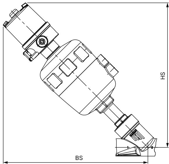
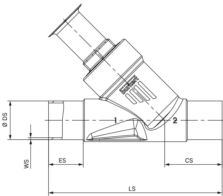
| Actuator Dimension | Parameter Value (Actuator Size 50 mm / D, DN25) |
|---|---|
| Actuator Outer Diameter (∅ A) | 64 mm |
| Centerline to Top of Actuator (B / H) | 152 mm (max.) |
| Centerline to Pilot Connection (K / M) | 136 mm (max.) |
| Pilot Air Connection Thread (P) | G 1/4 |
| Total Height from Pipe Base (BS / HS) | 223 mm (max.) |
| Welded End Dimension | DIN 11850 Series 2 / DIN 11866 Series A / DIN EN 10357 Series A |
|---|---|
| Pipe External Diameter (∅ DS) | 29.0 mm |
| Wall Thickness (WS) | 1.5 mm |
| Face-to-Face Body Length (LS) | 130 mm |
| Centerline to Port End (CS) | 43 mm |
| Straight Weld Extension (ES) | 26 mm |
| Hexagon Nut Across Flats (WAF) | 41 mm |
Burkert 20061740 can be installed in any orientation, though positioning the actuator upright is recommended to avoid particulate settling within the neck bushing.
Dismount Actuator Prior to Welding
Before welding the CF3M body into the process line, the pneumatic actuator assembly must be detached from the valve body. Applying welding heat to a fully assembled valve will permanently distort the PA housing, damage internal NBR piston seals, and destroy the PTFE spindle packings.
The pilot connection housing can be rotated steplessly through 360° to accommodate pipe routing. To reposition:
Connect the pilot medium (instrument-grade compressed air or dry neutral gas) to the lower pilot port on the actuator cylinder base. In corrosive wash-down environments, connect a pneumatic vent hose to the upper exhaust port to vent into a non-aggressive zone.
| Port Identification | Connection Assignment (Control Function A) |
|---|---|
| Port 1 (Lower Actuator Port) | Pilot air supply inlet (G 1/4) |
| Port 2 (Upper Actuator Port) | Atmosphere exhaust / breathing filter vent |
Verify that the supply line delivers a steady pressure between 4.1 bar and 10 bar. Cycle the valve several times under dry conditions before admitting process media. Check the optical position indicator on top of the actuator transparent bonnet: the red indicator stem rises when the valve strokes open.
Under clean media conditions, the Type 2000 valve mechanism operates maintenance-free. Periodic visual inspections should verify system tightness during plant maintenance shutdowns.
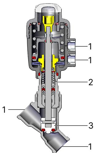
| Inspection Checkpoint | Potential Failure Mode | Corrective Action |
|---|---|---|
| Process Pipeline Joint (1) | Pipe connection leakage | Check weld joints or flange/clamp seals |
| Actuator Relief Bore (2) | Spindle packing leakage | Replace packing gland seal set or actuator |
| Valve Seat / Swivel Plate (3) | Internal cross-seat leakage | Replace valve disc set (swivel plate & PTFE seal) |
| Body Joint Sealing Plane | Body seal leakage | Replace graphite body gasket; check 60 Nm torque |
| Fault Condition | Probable Cause | Corrective Remedial Action |
|---|---|---|
| Actuator fails to stroke | Pilot pressure below 4.1 bar | Increase pilot air supply pressure to 4.1–10.0 bar |
| Pilot line routed to upper port | Reconnect pilot air supply to lower port (Port 1) | |
| Process pressure exceeds 5.2 bar | Lower medium pressure to within 5.2 bar rating | |
| Pipeline flow reversed | Verify flow enters beneath seat per body arrow | |
| Internal seat leakage when closed | Debris trapped in valve seat | Flush pipework; install an upstream Y-strainer |
| PTFE seat disc worn or scored | Replace swivel plate valve set | |
| Pilot air venting sluggish | Check pilot solenoid valve exhaust port for blockage | |
| External leakage at relief bore | PTFE packing gland worn | Replace spindle packing gland set using tool 639166 |
Explore similar products in our catalog



