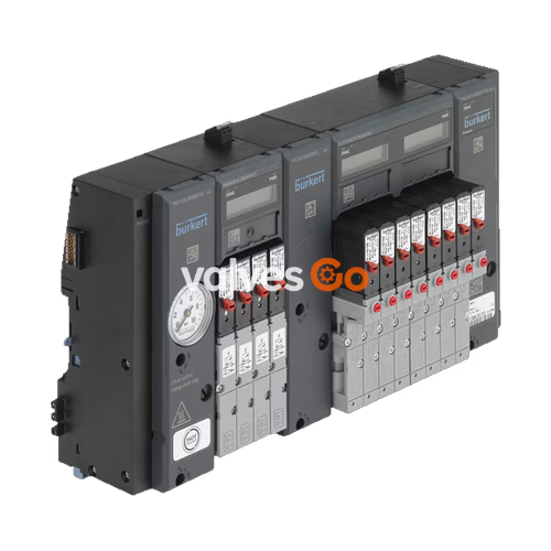
BURKERT 20061888 is a dedicated Revision 2 (REV.2) build of the Type 8647 AirLINE SP electropneumatic automation system, configured with 24 valve slots on an 11 mm width grid. It incorporates 24 Type 6524 double valves (2x 3/2-way normally closed, Circuit Function C C), yielding a total of 48 independently actuated valve functions. Pneumatic supply and exhaust connections use G 1/4 female threads, while working connections feature D6 push-in fittings routed directly through an AirLINE Quick stainless steel floor adapter plate (material 1.4301 with 1.4401 working connectors). The system operates from 2.5 to 10 bar pressure with 24 V DC electrical supply and connects mechanically and electrically to Siemens SIMATIC ET 200SP distributed peripheral systems.
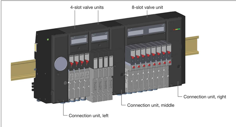
System Architecture and Product Configuration
Type 8647 AirLINE SP combines connection units, pneumatic base modules, electronic base modules (PQ modules), and pilot valves into a unified terminal. Article 20061888 is factory-configured for high-density cabinet floor installations requiring corrosion-resistant fluid interfaces.
Station Capacity and Valve Composition
- Station width: 11 mm grid per station across all 24 slots.
- Integrated pilot valves: 24 Type 6524 double valves, each housing two flipper-actuated pilot stages (Type 6144) driving pneumatic seat valve amplifiers in normally closed resting state.
- Valve functions: 48 active pilot channels across 24 physical slots.
- Intermediate feed: 1 intermediate feed unit (PSU-M) integrated into the block. System rules require an intermediate pneumatic supply after every 16 valve functions when using 2x 3/2-way valves, ensuring uniform air distribution across the 48 channels.
- Pneumatic base modules: 4-slot pneumatic base blocks equipped with D6 push-in couplings.
Generation Revision 2 (REV.2) Distinctive Features
Article 20061888 belongs to Revision 2 (REV.2) of the Type 8647 series. Key mechanical and operational differences from REV.1 include:
- Standardized Flange Profile: The pneumatic interface between pilot valves and base modules uses the unified FM20 profile across both single and double valves.
- Working Port Geometry: Working connections 2 (A) and 4 (B) feature a wavy arrangement on the base module face rather than the parallel arrangement found on REV.1.
- Hose Collet Identifier: Push-in coupling release rings are blue (REV.1 used black release rings).
- Flow Reduction Factor: When equipped with optional HotSwap P shut-off check valves, flow reduction in REV.2 is limited to approximately 20% (compared to up to 50% in REV.1).
Flange Compatibility
REV.1 and REV.2 single valves are mechanically keyed and incompatible. For 2x 3/2-way double valves (Type 6524), replacement valves use the FM20 flange interface (article 204710 with manual override or 300818 without manual override).
Technical Specifications
| Specification Parameter | Value / Condition |
|---|
| Article number | 20061888 |
| Valve island type | Type 8647 AirLINE SP |
| Product generation | Revision 2 (REV.2) |
| Number of valve slots | 24 stations (11 mm pitch) |
| Total valve functions | 48 (24x 2x 3/2-way Type 6524) |
| Circuit function | C C (dual 3/2-way, normally closed) |
| Manual override | Standard push/turn function |
| Flow rate ($Q_{Nn}$ value air) | 300 l/min (measured at +20 °C, 6 bar inlet, 1 bar differential) |
| Operating pressure range | 2.5 bar to 10 bar (overpressure to atmospheric) |
| Operating medium | Dry compressed air (lubricated or unlubricated), neutral gases |
| Compressed air quality | ISO 8573-1:2010, Class 7.4.4 (5 µm filtration recommended) |
| Operating voltage | 24 V DC (±10% allowable tolerance, max. residual ripple 2.4 Vss) |
| Nominal power per valve | 2x 0.8 W (with automated power reduction after 120 ms) |
| Holding current per coil | 28 mA (inrush current 40 mA) |
| Medium temperature | 0 °C to +50 °C |
| Ambient operating temperature | 0 °C to +55 °C |
| Storage temperature | -20 °C to +60 °C |
| Permissible humidity | 75% average, 85% occasionally, non-condensing |
| Degree of protection | IP20 (terminal); IP65 in closed control cabinet; UL Type 4X via AirLINE Quick |
| Protection class | Class III according to DIN EN 61140, VDE 0140 |
| Supply / exhaust connection | G 1/4 female thread |
| Working connections | D6 push-in couplings |
| Adapter plate material | Stainless steel 1.4301 |
| Working connector material | Stainless steel 1.4401 |
| Body material | Polyamide (PA) and Polycarbonate (PC) |
| Valve seal material | FKM, NBR, and PUR |
AirLINE Quick Stainless Steel Floor Adaptation
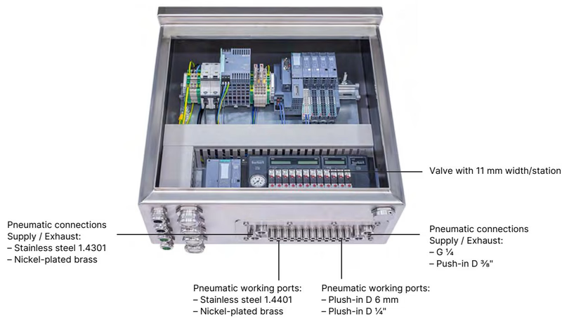
Article 20061888 integrates the AirLINE Quick adapter plate fabricated from 1.4301 stainless steel with 1.4401 stainless steel pneumatic push-in fittings. This design mounts the entire pneumatic terminal directly over a rectangular cutout in the floor or side wall of the control cabinet.
AirLINE Quick Advantages and Installation Limits
- Reduced Cabinet Envelope: Pneumatic working lines exit directly through the cabinet floor, eliminating bulkhead fittings, internal tubing bundles, and cabinet-side ducting.
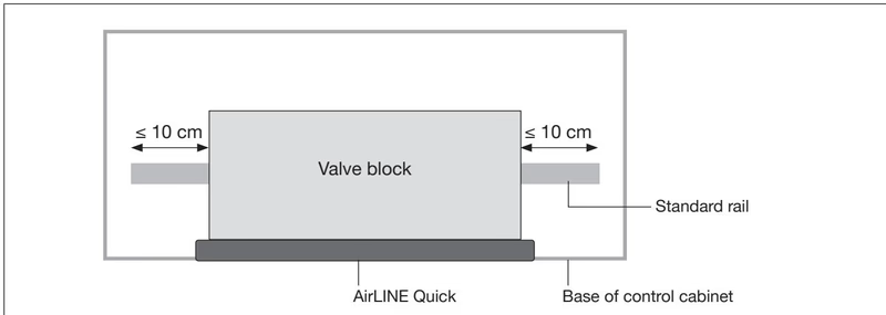
- Mechanical Support: When AirLINE Quick is utilized, the mechanical base plate carries the terminal and DIN rail rather than the rail supporting the valve island.
- Standard Rail Projection: The permissible lateral projection of the standard DIN rail is limited to 10 cm beyond both ends of the valve block.
- BaseUnit Restrictions: Only short Siemens BaseUnits can be installed on the supported rail sections.
- ET 200SP HA Restriction: Due to profile rail construction, AirLINE Quick cannot be combined with SIMATIC ET 200SP HA.
Installation Procedure for AirLINE Quick
- Prepare a burr-free cutout in the control cabinet floor matching the 24-station AirLINE Quick plate dimensions.
- Verify the pre-fitted elastomeric sealing ring is seated in the plate groove without twisting or damage.
- Position the valve block assembly over the cutout from inside the cabinet.
- Fit the external stability plate from the outside and tighten the M5x10 fastening screws to 2.0 Nm.
Pneumatic Connections and Installation Practice
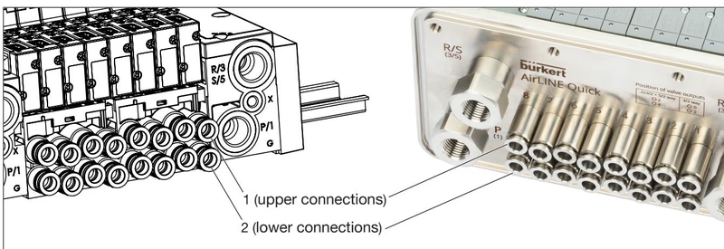
Port Allocation on Valve Units
For 2x 3/2-way valves (Type 6524), both upper and lower pneumatic working ports are active:
- Upper port (Position 1): Working connection 2 (A) for pilot stage 1.
- Lower port (Position 2): Working connection 4 (B) for pilot stage 2.
- Supply port 1 (P): G 1/4 inlet located on supply units (PSU-L, PSU-R, and central feed PSU-M).
- Exhaust ports 3 (R) / 5 (S): G 1/4 threaded ports for system venting.
- Pilot exhaust / auxiliary control port (X): M5 threaded port.
Port Tightening Torques
| Connection | Port Thread | Recommended Torque | Maximum Permissible Torque |
|---|
| Supply & exhaust (P, R/S) | G 1/4 | 4.0 Nm to 7.0 Nm | 20.0 Nm |
| Auxiliary pilot air (X) | M5 | 1.0 Nm to 1.2 Nm | 3.0 Nm |
| AirLINE Quick push-in fitting | M7 | 1.75 Nm to 2.25 Nm | 4.0 Nm |
Tubing and Push-in Connector Assembly (ISO 14743)
To ensure positive retention and leak tightness in the D6 push-in connectors, follow standard DIN EN ISO 14743:2020 specifications:
- Outer Diameter Tolerance: Outer diameter must remain within ±0.08 mm for 6 mm polyamide (PA) tubing and ±0.1 mm for 6 mm polyurethane (PU) tubing.
- Tube Preparation: Cut tubing square at 90°. Diagonal cuts reduce mechanical holding forces and can cause seal leakage.
- Insertion Force: Push the hose firmly into the fitting until it passes the internal O-ring and bottoms against the tube stop. Polyamide 6 mm tubing requires a minimum pull-off retention of 120 N; polyurethane 6 mm tubing requires 100 N.
- Support Sleeves: For soft or flexible PU tubing under heavy duty cycles, insert support sleeves (article 20099400) to reinforce the tube wall inside the collet.
Siemens SIMATIC Integration and Fieldbus Configuration
Type 8647 AirLINE SP acts as an integrated station member of the Siemens SIMATIC ET 200SP distributed peripheral family. Communication occurs directly over the ET 200SP backplane bus, while coil excitation is drawn from the internal power bus.
System Extension and Configuration Rules
- Power Supply Segregation: Valves operate within a tight voltage tolerance of 24 V DC ±10%. Install a light-colored Siemens BaseUnit (type code BU...D or BU...D/T) immediately upstream (to the left) of the valve island to establish an independent potential group.
- Subsequent BaseUnits: If additional ET 200SP standard I/O modules are placed to the right of the valve block, the first BaseUnit to the right must also be a light-colored unit (BU...D or BU...D/T), because the power bus is not carried across the right connection interface of the valve block.
- Engineering Software Integration:
- TIA Portal: Integrated via Hardware Support Package HSP0225 (from TIA Portal V14 SP1) or GSDML.
- STEP 7 Classic: Integrated via HSP2105 (STEP 7 V5.5 SP4 or higher) or GSD.
- SIMATIC PCS 7: Integrated via Hardware Update Package HUP (from PCS 7 V9.0 SP2).
Process Data Architecture for Electronic Base Modules (PQ Modules)
Each electronic base module provides process image mapping according to selected operating modes:
- Standard Mode (ST): Binary control of coil outputs and channel-level Quality Information (QI) electrical feedback.
- Position Feedback Mode (PF): Maps digital feedback switch states (end positions A and B) from field valves directly into the process image for visualization on the module LC display.
- Pressure Indicator Mode (PI): Transfers analog pressure values and pressure QI from supply units (PSU-...-PS) to the base module display.
Safety Shutdown and Electrical Diagnostics
Shutdown Architectures
- Channel-Level Shutdown (SIA): Optional Type 6524 variants with flying leads allow discrete hardwired de-energization of individual valves via external safety relays.
- Module-Level Shutdown (EVS): Electronic base modules equipped with the 2-pole pluggable screw terminal (EVS) allow interruption of load voltage to all valves on that module using a potential-free contact.
- Block-Level Fail-Safe Shutdown (F-PM-E): Operates within the potential group of a Siemens fail-safe power module (F-PM-E 24VDC/8A PPM ST). Both the PQ base modules and PSU connection units marked "FC" support fail-safe power disconnection, returning all Type 6524 NC valves to their safe resting state.
EVS Wiring Restrictions
Connect each EVS terminal solely to a potential-free contact (such as a relay output). Never interconnect multiple EVS terminals together, and do not apply external voltage to the EVS pins. Maintain physical segregation from power wiring to prevent capacitive or inductive coupling.
Visual and Fieldbus Diagnostics
- PWR OK LED: Located on left connection unit PSU-L, illuminated green when supply voltage is within tolerance (≥ 21.6 V DC).
- DIAG LED: Two-color LED on PQ modules indicating module configuration and fault states (solid green: operational; flashing red: active channel diagnostic).
- Graphics LC Display: Shows graphical channel switching status (channels 0–7 and 8–15), feedback positions, and plain-text diagnostics (e.g., "Wire Break", "Short Circuit", "EVS active", "PROFIenergy").
- Dual Switching Cycle Counters: Tracks operating cycles separately for the pilot valve solenoid and the connected pneumatic actuator, triggering maintenance alarms when preset thresholds are reached.
Ordering Chart and Spare Parts
| Item / Description | Content / Packaging | Article Number |
|---|
| Valve island Type 8647 11 mm 24-bank ALQ VA (REV.2, 24x 2x 3/2 NC, G 1/4, D6) | Complete pre-assembled terminal | 20061888 |
| Replacement valve Type 6524 2x 3/2-way NC (2.5–10 bar, 24 V DC, FM20 flange) | 1 piece | 204710 |
| Replacement valve Type 6524 2x 3/2-way NC without manual override (2.5–10 bar) | 1 piece | 300818 |
| Slot cover plate for Type 6524 2x 3/2-way valve (REV.2) | 1 piece | 661092 |
| Electrical connection cover plate (all valve slots) | 1 piece | 653670 |
| Valve profile seal set FM20 for Type 6524 2x 3/2-way (FKM/NBR) | 12 pieces | 20016305 |
| Module seal set MP16 for pneumatic base modules (REV.2) | 4 pieces | 20024339 |
| AirLINE Quick blind plate, 24-fold with intermediate feed cutout | 1 piece | 20057394 |
| Left interface set for Type 8647 | 1 set | 20029826 |
| Push-in tube connector D6 mm (stainless steel VA) | 8 pieces | 20024341 |
| Support sleeves for 6 mm OD flexible PU tubing | 1 pack | 20099400 |