PN25

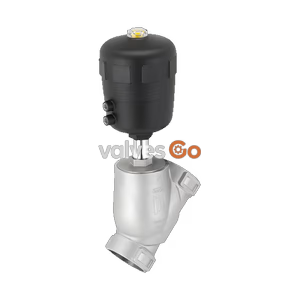
BURKERT Type 3321 electromotive 2/2-way globe valve features rapid shut-off, safety position via SAFEPOS energy-pack, and fieldbus compatibility.
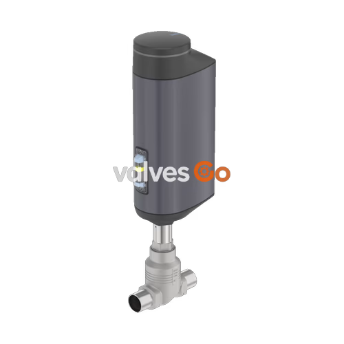
BURKERT Type 3321 is an innovative process on/off valve designed for shut-off tasks under demanding operating conditions. The electromotive actuator of the globe valve with ball screw moves the swivel plate to the desired end position at a particularly high speed up to 6 mm/s, reacting almost instantaneously to process signals. If necessary, the safety position can be approached by an optional energy storage (SAFEPOS energy-pack) in case of power failure. The electromotive actuator and shut-off valve are adapted perfectly to each other with a closed design and robust surface, ensuring the hygienic requirements of fast and residue-free cleaning.
Harsh ambient conditions are no problem for the electromotive globe valve Type 3321 due to the degree of protection IP65/IP67 and high impact and vibration resistance. Thanks to the tried-and-tested, self-adjusting packing gland with exchangeable V-seals, the globe valve achieves maximum service life and tightness. The fieldbus-compatible Type 3321 shut-off valve offers the operator many helpful functions for process monitoring, valve diagnostics, and preventive maintenance.
| Product properties | Value |
|---|---|
| Design | Globe on/off valve |
| Nominal diameter | DN 15...DN 100, NPS 1/2...4 |
| Safety setting in case of power failure | With SAFEPOS energy-pack: open, closed or freely programmable position. Without energy storage: blocked in last position |
| Flow direction | Against closing direction (below seat) |
| Operating pressure | 0...25 bar(g). Vacuum variant: -0.9 bar(g) (optional) |
| Nominal pressure | PN 25 (DIN EN 1333), Class 150 (DIN EN 1759) |
| Seat leakage | Leakage rate A (DIN EN 12266-1), seat seal PTFE and PEEK, test medium air |
| Kv value | 4.7...165 m3/h |
| Closing time | AG2: 2.3...6.6 s. AG3: 8.7 s |
| Travel speed | 6 mm/s (AG2 1300 N), 4 mm/s (AG2 2500 N), 3 mm/s (AG3 7700 N and 10000 N) |
| Operating voltage | 24 V DC ± 10 % (maximum residual ripple 10 %) |
| Fieldbus (digital) | Bürkert system bus (büS) (standard), CANopen (optional), EtherNet/IP, PROFINET, Modbus TCP, EtherCAT (optional via integrated gateway) |
| Medium temperature | -40 °C...+ 230 °C |
| Ambient temperature | -25 °C...+65 °C (only without additional modules) |
| Degree of protection | IP65/IP67 (DIN EN 60529), NEMA 4X |
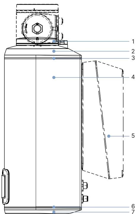
Actuator Materials:
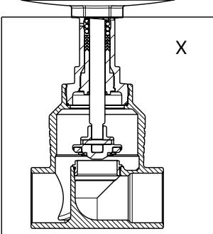
Valve Body Materials:
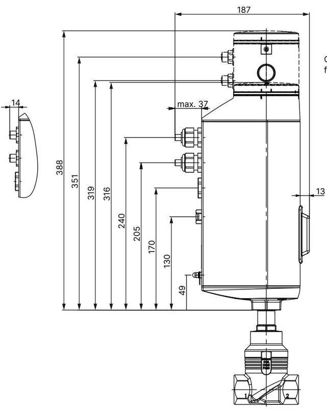
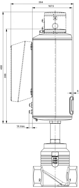
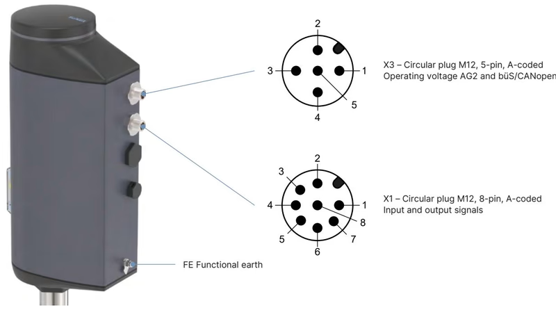
The actuator position is controlled according to the digital input. The selection is made either by an external standard signal or via a fieldbus (digital). The device features 1 digital input and 2 digital outputs.
| DN | NPS | Actuator force [N] | Max. operating pressure PTFE [bar(g)] | Max. operating pressure PEEK [bar(g)] | Kv value water [m3/h] |
|---|---|---|---|---|---|
| 15 | 1/2 | 1300 | 25 | 25 | 4.7 |
| 20 | 3/4 | 1300 | 25 | 25 | 8.1 |
| 25 | 1 | 1300 | 25 | 25 | 13 |
| 32 | 1 1/4 | 1300 / 2500 | 16 / 25 | 16 / 25 | 18 |
| 40 | 1 1/2 | 1300 / 2500 / 7700 | 10 / 18 / - | 10 / 18 / 25 | 31 |
| 50 | 2 | 1300 / 2500 / 7700 | 6 / 10 / - | 6 / 10 / 25 | 45 |
| 65 | 2 1/2 | 10000 | - | 25 | 73 |
| 80 | 3 | 10000 | - | 17 | 110 |
| 100 | 4 | 10000 | 13.5 | 10.5 | 165 |
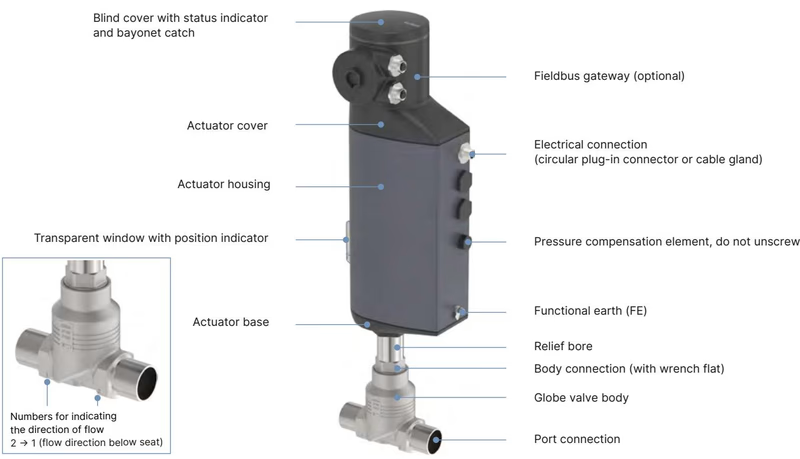
The electromotive linear actuator consists of a brushless DC motor, a gear, and a spindle system that transfers the force to the closing element. The integrated control electronics are controlled either by standard signals or via a fieldbus (digital). The valve position can be changed manually in 2 ways: either via the electrical manual control or via a mechanical manual override if no supply voltage is available.
WARNING
Risk of injury from high pressure. Before working on the system or device, switch off the pressure and vent or drain lines.
DANGER
Risk of injury from discharge of medium and release of pressure. It is dangerous to remove a device which is under pressure due to the sudden release of pressure or discharge of medium. Before removing a device, switch off the pressure and deaerate lines.
Explore similar products in our catalog