


PN25

Burkert 20074958 (Type 3321) is an electromotive 2/2-way on/off globe valve with 24 V DC AG2 actuator, DN 32 welded ports, PTFE seat seal, SAFEPOS energy-pack safety shut-off, and IP65/IP67 enclosure.
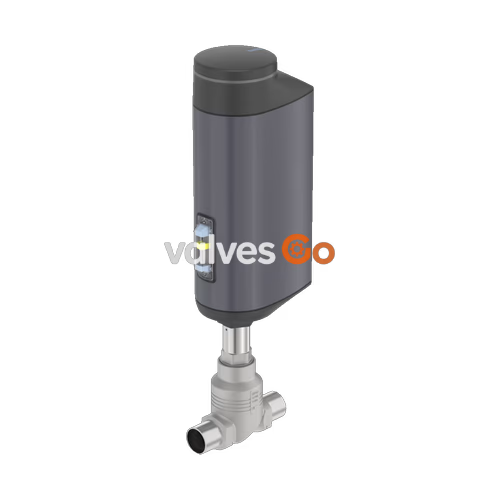
BURKERT 20074958 (Type 3321) is an electromotive 2/2-way on/off globe valve designed for media shut-off in demanding industrial and hygienic fluid applications. Operating on 24 V DC, the valve utilizes an electromotive linear actuator with an integrated ball screw mechanism to position the valve swivel plate at speeds up to 6 mm/s. The unit integrates an AG2 actuator size providing a nominal driving force of 1300 N, delivering tight closure against operating pressures up to 16 bar(g) with flow oriented below the seat. Standard execution includes the SAFEPOS energy-pack emergency storage module, automatically moving the valve to a predefined normally closed safety position if electrical supply power is interrupted.
The process interface of article 20074958 is configured with DN 32 (NPS 1 1/4) welded pipe ends compliant with DIN EN ISO 1127 / ISO 4200 / DIN 11866 series B (pipe outer diameter 42.4 mm, wall thickness 2.0 mm). Constructed with a cast stainless steel CF3M globe body, stainless steel internal trim, and a PTFE seat seal, the assembly achieves leakage rate A tightness according to DIN EN 12266-1. The ingress protection rating of IP65/IP67 and NEMA 4X, combined with an Ecolab-tested housing surface, ensures resistance to washdown procedures, weather exposure, and mechanical impacts in automated process plants.
| Parameter | Specification Details |
|---|---|
| Manufacturer Type | 3321 |
| Article Number (SKU) | 20074958 |
| Valve Design | 2/2-way electromotive globe on/off valve |
| Nominal Diameter | DN 32 (NPS 1 1/4) |
| Port Connection Type | Welded pipe connection |
| Port Connection Standard | DIN EN ISO 1127 / ISO 4200 / DIN 11866 series B (42.4 x 2.0 mm) |
| Actuator Size / Driving Force | AG2 / 1300 N |
| Operating Voltage | 24 V DC ±10% (maximum residual ripple 10%) |
| Operating Current | Maximum 3 A (including 1 A SAFEPOS charging current; +2 A at min. temperature) |
| Standby Power Consumption | 2 to 4 W |
| Duty Cycle | 100% continuous duty |
| Protection Class | Class III per DIN EN 61140 |
| Flow Direction | Below seat (against closing direction, port 2 → 1) |
| Nominal Pressure Rating | PN 25 (DIN EN 1333), Class 150 (DIN EN 1759) |
| Operating Pressure Range | 0 to 16 bar(g) |
| Flow Coefficient Kv (Water) | 18.1 m³/h (per DIN EN 60534-2-4) |
| Flow Coefficient Cv | 20.9 gpm |
| Seat Orifice Diameter | 32 mm (1 1/4") |
| Seat Leakage Class | Leakage rate A (DIN EN 12266-1, test medium air) |
| Medium Temperature Range | -10 °C to +130 °C |
| Ambient Temperature Range | -25 °C to +65 °C (refer to derating curves) |
| Typical Closing Time | 4.1 s (travel speed 6 mm/s) |
| Safety Position on Power Loss | Normally closed (NC) via integrated SAFEPOS energy-pack |
| Ingress Protection Rating | IP65 / IP67 (DIN EN 60529), NEMA 4X |
| Control Signals | Binary: 1 digital input (0-5 V log 0, 10-30 V log 1), 2 digital outputs (100 mA) |
| Diagnostic Communication | büS service interface (Bürkert Communicator software Type 8920) |
| Food Conformity | EC Regulation 1935/2004 compliant per manufacturer declaration |
| Detergent Resistance | Tested according to Ecolab test method F&E/P3-E No. 40-1 |
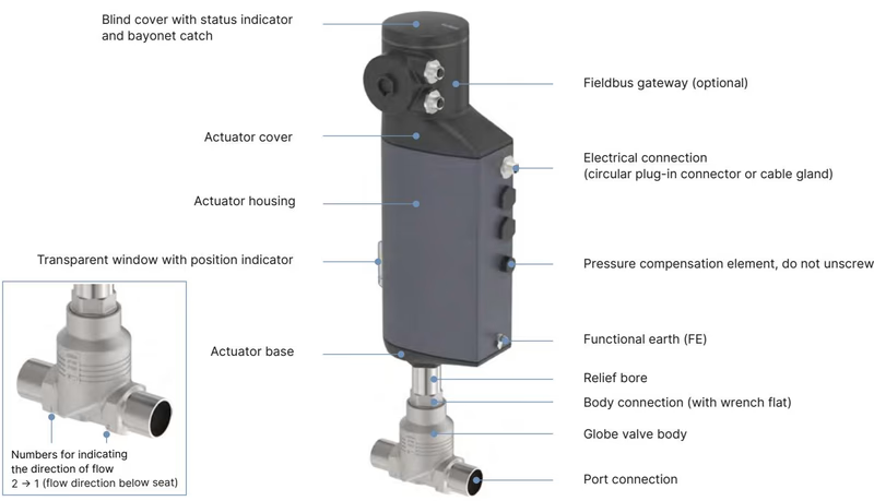
The electromotive valve comprises an AG2 actuator mechanism and a fluidic globe valve assembly. The external surfaces and fluid-wetted components are manufactured from industrial-grade alloys and polymers engineered for chemical resistance and cleanability.
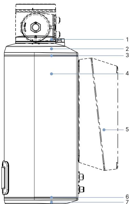
| Item No. | Component Part | Material |
|---|---|---|
| 1 | Blind cover / gateway housing | PPS (standard) / stainless steel 1.4301 (ATEX/IECEx variants) |
| 2 | Actuator cover | PPS |
| 3 | Seal | EPDM |
| 4 | Actuator housing | Powder-coated aluminium |
| 6 | Seal | EPDM |
| 7 | Actuator base | PPS |
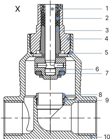
| Item No. | Component Part | Material |
|---|---|---|
| 1 | Spindle | Stainless steel 1.4401 (316) / 1.4404 (316L) |
| 2 | Spindle seal | PTFE V-seals (filled) with spring compensation |
| 3 | Spindle guide | PEEK or stainless steel 1.4404 (316L) |
| 4 | Packing gland tube | Stainless steel 1.4401 (316) |
| 5 | Seal valve body | Graphite or PTFE |
| 6 | Swivel plate | Stainless steel 1.4571 |
| 7 | Valve seat seal | PTFE seal washer (PEEK optional for >+130 °C) |
| 8 | Valve seat | Stainless steel 1.4571 |
| 9 | O-ring valve seat | EPDM or PTFE |
| 10 | Valve body | Cast stainless steel CF3M |
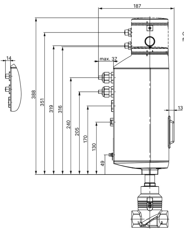
Dimensions are stated in millimetres. The actuator is mounted directly on the CF3M globe body connection. In the fully closed position, the actuator spindle mechanism is raised by approximately 2 mm.
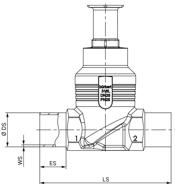
| DN | NPS | Standard Height H1 (mm) | Height with Fieldbus Gateway H2 (mm) |
|---|---|---|---|
| 10 | 3/8 | 417 | 489 |
| 15 | 1/2 | 417 | 489 |
| 20 | 3/4 | 423 | 495 |
| 25 | 1 | 427 | 498 |
| 32 | 1 1/4 | 448 | 519 |
| 40 | 1 1/2 | 452 | 524 |
| 50 | 2 | 485 | 557 |
| DN | Weld Socket Depth ES (mm) | Face-to-Face Length LS (mm) | Pipe Outside Diameter ∅ DS (mm) | Wall Thickness WS (mm) |
|---|---|---|---|---|
| 10 | 20 | 90 | 17.2 | 1.6 |
| 15 | 20 | 90 | 21.3 | 1.6 |
| 20 | 20 | 100 | 26.9 | 1.6 |
| 25 | 26 | 130 | 33.7 | 2.0 |
| 32 | 26 | 140 | 42.4 | 2.0 |
| 40 | 26 | 150 | 48.3 | 2.0 |
| 50 | 26 | 175 | 60.3 | 2.0 |
| 65 | 26 | 210 | 76.1 | 2.3 |
| 80 | 26 | 230 | 88.9 | 2.3 |
| 100 | 26 | 260 | 114.3 | 2.6 |
The device uses circular plug-in connectors located on the AG2 actuator base for power supply and control signalling.
| Pin | Signal Assignment |
|---|---|
| 1 | Digital input + (0 to 5 V = log "0", 10 to 30 V = log "1") |
| 2 | GND for digital input and digital outputs |
| 3 | Digital output 2 + (current limitation 100 mA) |
| 4 | Digital output 1 + (current limitation 100 mA) |
| 5 | Do not connect |
| 6 | Do not connect |
| 7 | Do not connect |
| 8 | Do not connect |
| Pin | Signal Assignment |
|---|---|
| 1 | CAN Shield / shield |
| 2 | Operating voltage 24 V DC ±10% |
| 3 | GND / CAN_GND |
| 4 | CAN_H |
| 5 | CAN_L |
büS Configuration Interface
The büS service interface, accessible beneath the blind cover, connects to a PC using an optional USB-büS interface set (article no. 772426). Detailed diagnostics, operating hours, cycle counters, and parameter sets are accessed via the Bürkert Communicator software (Type 8920).
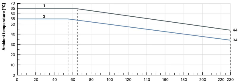
The operational envelope of Type 3321 is governed by medium temperature, operating pressure, and ambient thermal loading:
BURKERT 20074958 includes the SAFEPOS energy-pack emergency storage module. In the event of an electrical power failure, stored energy drives the valve into the safety position (configured as normally closed). The energy pack reaches full operational charge within a maximum of 120 seconds after 24 V DC power is applied.
For commissioning, servicing, or power-off handling, the valve offers two manual override methods:
Torque Limitation on Mechanical Manual Drive
Do not exceed the maximum tightening torque of 2 Nm on the mechanical manual control. Exceeding this limit will cause mechanical damage to the internal gearing. Operate the mechanical manual control only when the device is completely de-energized.
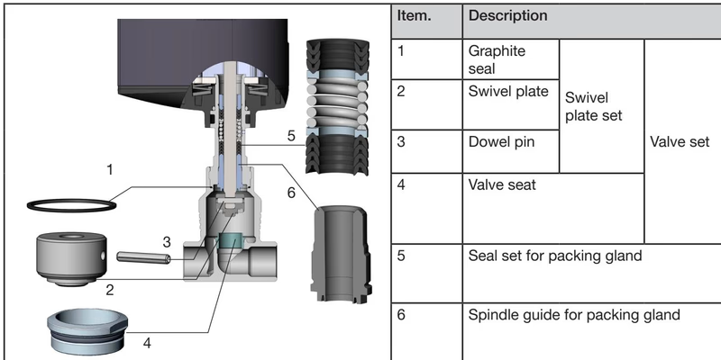
| Fastener / Connection Location | Tool / Dimension | Specified Tightening Torque |
|---|---|---|
| Valve body to body connection (DN 32) | Open-end wrench | 65 ±3 Nm |
| Spindle guide for packing gland (spindle ∅ 10 mm) | Modified socket wrench | 6 Nm |
| Valve seat installation (DN 32, uncoated) | Seat installation tool | 80 Nm (+5 Nm) |
| Valve seat installation (DN 32, coated) | Seat installation tool | 65 Nm (+5 Nm) |
| Actuator base to housing screws (4x) | Hex key | 5 Nm (tighten crosswise) |
| Mechanical manual override | 4 mm Allen key | Maximum 2 Nm |
Lubrication Paste Recommendation
Before reassembly, grease the external thread of the body connection, the spindle guide thread, and the valve seat threads with Klüber paste UH1 96-402. For oxygen or high-purity applications, verify that only certified application-specific lubricants are used.
After replacing the valve body or disassembling the actuator stem, run the X.TUNE calibration routine to adapt the internal position controller to the physical valve stroke:
Never Run X.TUNE Under Process Pressure
Executing the X.TUNE routine while process medium pressure is present causes incorrect stroke calibration and uncontrolled process behavior. Depressurize and drain lines prior to initiating X.TUNE.
| Item Description | Article Number |
|---|---|
| SIM card for device parameter backup and transfer | 291773 |
| Holding device for body connection (DN 15 to DN 40) | 693770 |
| Replacement plastic blind cover | 277881 |
| SAFEPOS energy-pack replacement module (AG2) | 285834 |
| USB-büS interface set 1 (Type 8923) | 772426 |
| büS adapter cable (M12 to büS micro-USB, 0.3 m) | 774931 |
| M12 circular socket cable, 4-pin A-coded, 5 m (AG2 power supply without bus) | 918038 |
| M12 circular socket cable, 8-pin A-coded, 2 m (X1 digital I/O signals) | 919061 |
Explore similar products in our catalog



