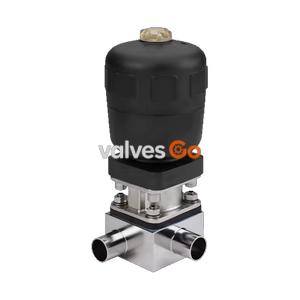
Type 2032

Burkert 20081992 Type 2935 manually operated tank bottom diaphragm valve. Features DN 150 flange, EPDM high-temperature diaphragm, CIP/SIP capable, and handles 0-10 bar.
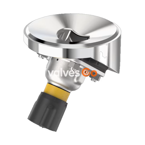
The Burkert 20081992 Type 2935 manually operated diaphragm valve consists of a manually operated actuator, a diaphragm, and a tank bottom valve body. The manual actuator with a plastic (PPS) or stainless steel handwheel is available with a diaphragm bonnet made of stainless steel or plastic, ensuring reliable use in hygienic or aggressive ambient conditions. The flow-optimised valve body with minimum dead space enables high flow values and a wide range of possible applications.
The actuator has a compact, autoclavable design and is equipped with an integrated visual position indicator, a reproducible stroke scale, and an adjustable closing limiter. The 20081992 variant features a DN 150 flange connection, an EPDM high-temperature diaphragm, and a stainless steel block material body (1.4435/316L), making it CIP and SIP capable for demanding sanitary processes.
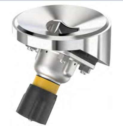
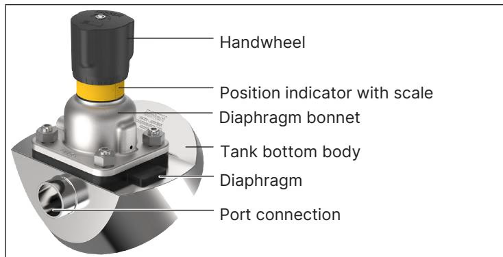
By manually overriding the handwheel, the force is transmitted via a spindle and the valve is opened or closed. Turning the handwheel anticlockwise opens the valve, turning it clockwise closes it. To protect the actuator, it is recommended not to close the actuator with more force than is required to close the valve tightly.
| Product Properties | Description |
|---|---|
| Block body material | Stainless steel block material 1.4435 according to DIN EN 10088 and 316L according to ASTM A479 / A479M |
| Diaphragm material | EPDM (AD), PTFE/EPDM (EA), advanced PTFE/EPDM (EU), laminate of GYLON® and EPDM (ER) |
| Actuator material | Stainless steel/PPS, PPS/PPS, stainless steel/stainless steel |
| Standard surface quality | Internally electrically polished: Ra ≤ 0.38 μm (ASME BPE SF4/DIN HE4); Internally mechanically polished: Ra ≤ 0.5 μm (ASME BPE SF1) |
| Operating medium | Neutral gases and liquids, highly purified, sterile, aggressive or abrasive mediums |
| Medium temperature (EPDM) | -10...+143 °C (steam sterilisation + 150 °C for 60 min) |
| Ambient temperature | -10...+130 °C (short-term up to + 150 °C), autoclavable |
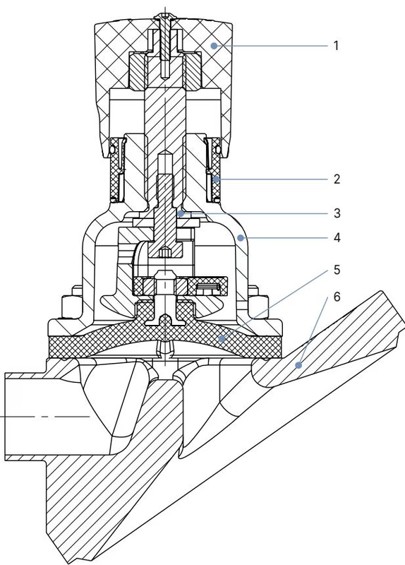
| No. | Element | Material |
|---|---|---|
| 1 | Handwheel | Polyphenylene sulphide (PPS), stainless steel 1.4308 |
| 2 | Visual position indicator | Polyamide (PA), stainless steel 1.4305 |
| 3 | Valve spindle | Stainless steel 1.4305 |
| 4 | Diaphragm bonnet | Stainless steel 1.4308, polyphenylene sulphide (PPS) |
| 5 | Diaphragm | EPDM (AD), PTFE/EPDM (EA), advanced PTFE/EPDM (EU), laminate of GYLON® and EPDM (ER) |
| 6 | Valve body | Stainless steel block material |
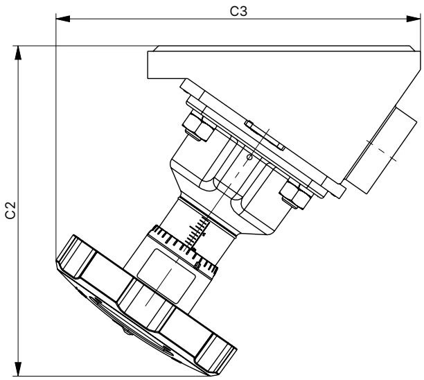
Note: Dimensions in mm, unless otherwise stated.
| Diaphragm size | C2 | C3 |
|---|---|---|
| 8 | 69 | 71 |
| 15 | 103 | 101 |
| 20 | 116 | 115 |
| 25 | 127 | 129 |
| 40 | 182 | 201 |
| 50 | 203 | 217 |
| 65 | 265 | 305 |
| 80 | 336 | 278 |
| 100 | 300 | 370 |
DANGER
Risk of injury due to high pressure and escaping medium. Switch off the pressure before working on the device or system. Vent or empty the lines.

Observe the following sequence:
TIP
Recommendations For information on containers and instructions for welding, refer to the ASME VIII Division I standard. Check the batch number indicated on the manufacturer’s certificate 3.1 supplied before starting welding work.
WARNING
Before welding, note the following:
For devices with the PX51 code (EPS 18 ATEX 2008 X / IECEx EPS 18.0007 X), the valve actuator is suitable for use as category 2 equipment in Zones 1/21 and 2/22.

DANGER
Explosion risk due to electrostatic discharge! If statically charged equipment or personnel suddenly discharge, there is a risk of explosion in potentially explosive atmospheres.
When used in accordance with the operating instructions, the actuator of the diaphragm valve is maintenance-free.
Inspection intervals:
Replacing the diaphragm:
Explore similar products in our catalog