


PN25

BURKERT 20090693 (Type 2961) is a manually operated 2-way globe control valve with DN 40 SMS 3008 welded ends, PTFE seat seal, parabolic plug, Kv 17.8 m³/h, and ATEX/IECEx and FDA/EC 1935/2004 compliance.
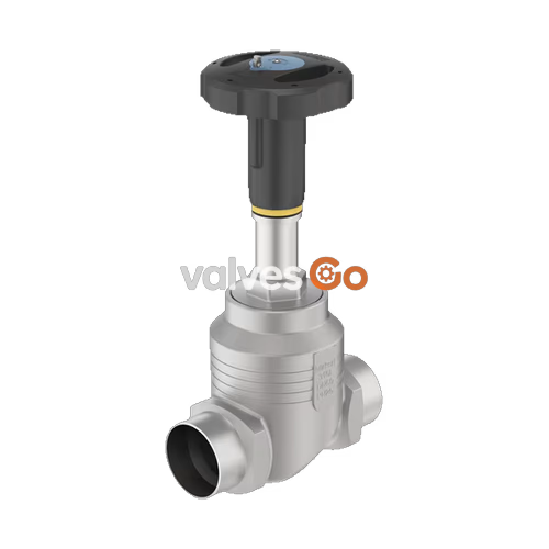
BURKERT 20090693 (Type 2961) is a manually operated 2-way globe control valve engineered for continuous flow regulation and shut-off in demanding industrial and hygienic media loops. The unit pairs a PPS (polyphenylene sulphide) manual actuator with an investment cast stainless steel 316L/CF3M globe valve body featuring SMS 3008 welded ends (DN 40, tube dimension 38.0 x 1.2 mm). Operating with fluid flow beneath the seat, the valve utilizes an interchangeable 32 mm stainless steel seat and an equal-percentage parabolic plug to deliver a calibrated flow coefficient ($K_v$) of 17.8 m³/h ($C_v$ 20.7 gal/min) with a theoretical rangeability of 50:1. Tight shut-off is ensured by a virgin PTFE soft seat seal conforming to DIN EN 60534-4 Leakage Class VI.
The self-adjusting packing gland incorporates spring-compensated PTFE V-rings that do not require manual adjustment over the service life of the valve. Visual feedback is provided by a dual-scale position indicator comprising a 50-division rotary dial on the handwheel and an exposed linear stroke scale. BURKERT 20090693 complies with the European Pressure Equipment Directive 2014/68/EU, meets EC 1935/2004 and FDA requirements for food contact, and holds ATEX and IECEx Category 2 non-electrical explosion protection ratings for Zone 1/21 and Zone 2/22 installations.

| Parameter | Specification |
|---|---|
| Product Type | Type 2961 Globe Control Valve |
| Article Number | 20090693 |
| Nominal Diameter | DN 40 (NPS 1 1/2) |
| Port Connection | Welded tube ends to SMS 3008 (38.0 mm OD x 1.2 mm wall) |
| Valve Body Material | Stainless steel 316L / CF3M |
| Actuator Material | Polyphenylene sulphide (PPS) |
| Handwheel Diameter | 110 mm (Actuator Size M) |
| Spindle Travel Per Turn | 1.75 mm |
| Nominal Valve Stroke | 26 mm |
| Seat Diameter | 32 mm (1 1/4") |
| Seat Seal Material | PTFE (Polytetrafluoroethylene) |
| Flow Coefficient ($K_v$) | 17.8 m³/h (water at +20 °C according to DIN EN 60534-2-4) |
| Flow Coefficient ($C_v$) | 20.7 gal/min |
| Flow Characteristic | Equal percentage ($n_g = 50:1$) |
| Seat Leakage Class | Class VI according to DIN EN 60534-4 (bubble-tight soft seal) |
| Nominal Pressure Rating | PN 25 (DIN EN 1333) / Class 150 (DIN EN 1759) |
| Operating Pressure Range | 0 bar(g) to 25 bar(g) |
| Fluid Temperature Range | -10 °C to +130 °C (derating applies at elevated temperatures) |
| Ambient Temperature Range | -10 °C to +60 °C |
| Permissible Fluid Viscosity | Max. 600 mm²/s |
| Spindle Interface | Spindle D14 |
| Stroke Limitation | None (standard base configuration) |
| Identification Marking | Data matrix code on type label |
BURKERT 20090693 complies with European harmonization legislation and international explosion proof and hygienic standards:
II 2G Ex h IIC T4...T2 Gb and II 2D Ex h IIIC T135 °C...T300 °C DbEx h IIC T4...T2 Gb and Ex h IIIC T135 °C...T300 °C Db| Temperature Class | Maximum Permissible Surface Temperature | Ambient Temperature Range | Maximum Permissible Fluid Temperature |
|---|---|---|---|
| T4 | +135 °C | -40 °C to +100 °C | +125 °C |
| T3 | +200 °C | -40 °C to +130 °C | +185 °C |
| T2 | +300 °C | -40 °C to +130 °C | +285 °C |
INFO
Operating parameters for BURKERT 20090693 with PTFE seat sealing are restricted by standard material properties to -10 °C to +130 °C medium temperature and -10 °C to +60 °C ambient temperature, which remains within the certified ATEX T4 envelope.
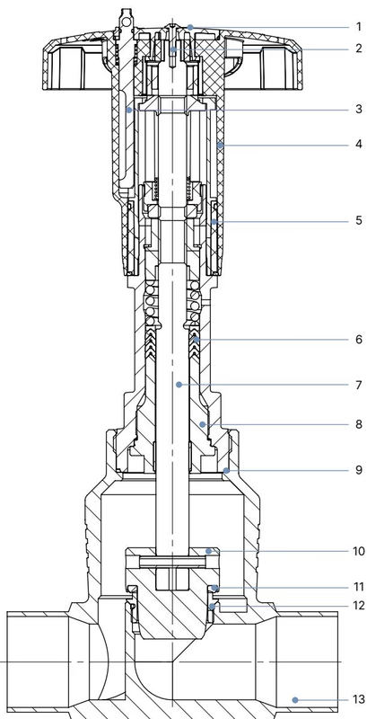
| Item | Component | Material Specification |
|---|---|---|
| 1 | Actuator Cover | Polyamide (PA) |
| 2 | Retaining Screw | Stainless steel 1.4301 |
| 3 | Locking Device (optional) | Stainless steel 1.4305 |
| 4 | Handwheel | Polyphenylene sulphide (PPS) |
| 5 | Visual Position Indicator & Scale | Polyamide (PA) |
| 6 | Packing Gland | Filled PTFE V-rings with spring compensation |
| 7 | Spindle / Stem | Stainless steel 1.4401 or 1.4404 |
| 8 | Spindle Guide | Stainless steel 1.4404 (316L), PTFE filled |
| 9 | Housing Body Seal | Graphite |
| 10 | Control Cone (Plug) | Stainless steel 1.4571 (316Ti) |
| 11 | Seat Seal | PTFE (soft seal for Leakage Class VI) |
| 12 | Valve Seat & O-Ring | Stainless steel 1.4571 seat, EPDM seal ring |
| 13 | Valve Body | Cast stainless steel 316L / CF3M |
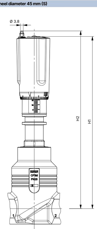
For pipe sizes DN 32 to DN 50, Type 2961 uses actuator Size M with a 110 mm diameter handwheel.
| Nominal Size DN | Nominal Size NPS | Handwheel ∅ (Size) | Overall Height H1 [mm] | Height with Interlock H2 [mm] |
|---|---|---|---|---|
| 15 | 1/2 | 45 mm (S) | 217 | 224 |
| 20 | 3/4 | 45 mm (S) | 224 | 230 |
| 25 | 1 | 45 mm (S) | 228 | 234 |
| 32 | 1 1/4 | 110 mm (M) | 296 | 303 |
| 40 | 1 1/2 | 110 mm (M) | 301 | 307 |
| 50 | 2 | 110 mm (M) | 307 | 313 |
| 65 | 2 1/2 | 160 mm (L) | 361 | 368 |
| 80 | 3 | 160 mm (L) | 369 | 375 |
| 100 | 4 | 160 mm (L) | 379 | 385 |
BURKERT 20090693 is equipped with SMS 3008 welded ends (outer diameter 38.0 mm, wall thickness 1.2 mm). Related welded body dimensions for the Type 2961 range are detailed below.
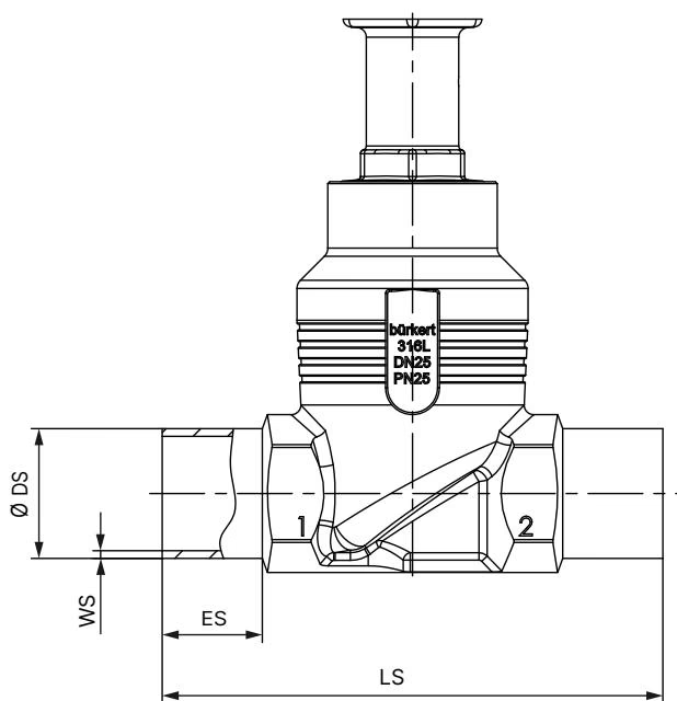
| DN | Port Type | Insertion Depth ES [mm] | Face-to-Face LS [mm] | Tube ∅ DS [mm] | Wall Thickness WS [mm] |
|---|---|---|---|---|---|
| 40 | SMS 3008 | 26 | 150 | 38.0 | 1.2 |
| 40 | DIN EN ISO 1127 / ISO 4200 | 26 | 150 | 48.3 | 2.0 |
| 40 | DIN 11850-2 / DIN 11866 series A | 26 | 150 | 41.0 | 1.5 |
| 40 | ASME BPE (NPS 1 1/2) | 26 | 140 | 38.1 | 1.65 |
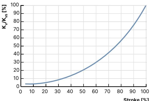
The flow profile conforms to DIN EN 60534-2-4 with flow entering beneath the valve plug. The valve retains an equal percentage characteristic down to $K_{vR}$ (the minimum $K_v$ value where characteristic tilt tolerance is maintained), established at 5% of stroke for seat sizes greater than 10 mm.
$K_v$ flow coefficient progression [m³/h] as a function of valve opening stroke for DN 40 globe control bodies with 110 mm handwheel (Size M):
| DN | Seat Size [mm] | Max. Pressure [bar] | Seat Seal | 5% | 10% | 20% | 30% | 40% | 50% | 60% | 70% | 80% | 90% | 100% | $K_{vs}$ [m³/h] |
|---|---|---|---|---|---|---|---|---|---|---|---|---|---|---|---|
| 40 | 25 | 25 | PTFE (VI) | 0.40 | 0.50 | 0.75 | 1.1 | 1.7 | 2.6 | 3.8 | 5.6 | 8.0 | 10.7 | 13.6 | 13.6 |
| 40 | 32 | 25 | PTFE (VI) | 0.48 | 0.60 | 0.85 | 1.3 | 2.1 | 3.2 | 4.6 | 6.9 | 11.0 | 15.0 | 20.0 | 20.0 |
| 40 | 40 | 25 | PTFE (VI) | 0.60 | 0.70 | 1.1 | 1.7 | 2.7 | 4.0 | 6.0 | 9.2 | 13.8 | 18.2 | 23.8 | 24.0 |
INFO
Article 20090693 is factory-calibrated for an operating $K_v$ rating of 17.8 m³/h ($C_v$ 20.7 gal/min) with a DN 40 port connection and a 32 mm seat opening, providing a 50:1 control turndown.
| Requirement | Seat Seal Material | Leakage Class (DIN EN 60534-4) | Medium Temperature Range | Application Scope |
|---|---|---|---|---|
| Bubble-tight shut-off | PTFE | Class VI | -40 °C to +130 °C | Liquids, steam, neutral and aggressive chemicals up to 130 °C |
| High-temperature tight shut-off | PEEK | Class VI | -10 °C to +230 °C | High-temperature steam and thermal fluids above 130 °C |
| Harsh process durability | Stainless steel | Class II | -40 °C to +230 °C | Abrasive or erosive media; 0.5% nominal flow leakage permitted |
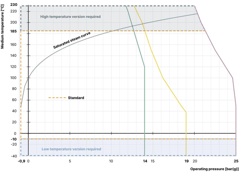
Maximum allowable operating pressures decrease with elevated fluid temperatures according to DIN EN 12516-1 (PN 25 rating) and ASME B16.34 (Class 150):
| Medium Temperature [°C] | PN 25 Body Derating [bar] | ASME Class 150 Derating [bar] | JIS 10K Derating [bar] |
|---|---|---|---|
| -10 to +38 / +50 | 25.0 | 19.0 | 14.0 |
| +100 | 24.5 | 16.2 | 14.0 |
| +130 / +150 | 22.4 | 14.8 | 13.4 |
| +200 | 20.3 | 13.7 | 12.4 |
| +230 | 19.0 | 12.7 | 11.7 |
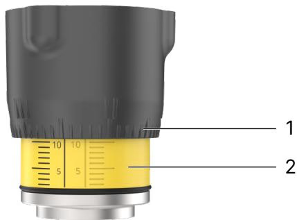
The manual actuator transmits user torque via a threaded spindle directly to the parabolic control cone. Rotating the handwheel counterclockwise lifts the plug against incoming medium pressure (flow below seat); rotating clockwise seats the valve.
DANGER
Depressurize pipelines, vent or drain process lines, and ensure zero line pressure before loosening body joints or disassembling actuators. Escaping pressurized or hazardous fluid can cause severe injuries.
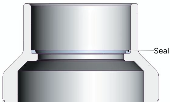
To prevent heat damage to internal PTFE and graphite seals during orbital or manual welding, detach the manual actuator from the valve body before welding:
WARNING
Do not use unapproved lubricants. For oxygen or food applications, apply only certified food-grade or oxygen-safe lubricants. Lubricate external body connection threads with Klüberpaste UH1 96-402.
| Valve Body Nominal Size DN | Tightening Torque [Nm] | Tolerance [Nm] |
|---|---|---|
| 10 / 15 | 45 | ±3 |
| 20 | 50 | ±3 |
| 25 | 60 | ±3 |
| 32 | 65 | ±3 |
| 40 | 65 | ±3 |
| 50 | 70 | ±3 |
| 65 | 100 | ±3 |
| 80 | 120 | ±5 |
| 100 | 150 | ±5 |
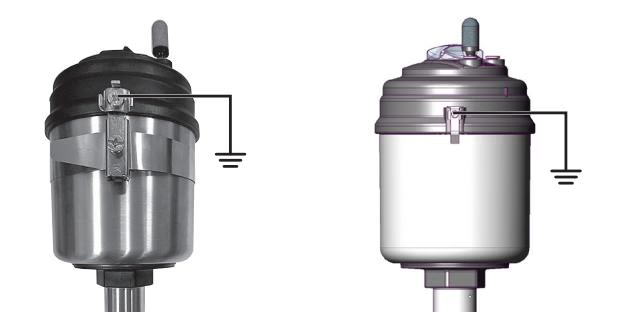
When deployed under variable code PX51 in Zone 1/21 or Zone 2/22, the following mechanical explosion protection measures must be implemented:
Under normal operating conditions with clean process media, the manual actuator is maintenance-free. Conduct an external visual inspection annually. Muddy or abrasive media require shorter inspection intervals.
| Malfunction | Root Cause | Remedial Action |
|---|---|---|
| Seat leakage across closed valve | Particulates or debris trapped between plug and seat | Flush line; install upstream strainer or dirt trap |
| PTFE seat seal worn or deformed | Replace the closure member / seat seal kit | |
| Reverse flow orientation | Reinstall valve ensuring flow arrives below seat (follow flow arrow) | |
| Operating differential pressure exceeds 25 bar | Verify system operating pressure against type label limits | |
| External leakage at relief bore | Spindle packing gland V-rings worn | Replace spindle packing gland set |
| Stiff or binding handwheel | Spindle threads contaminated or unlubricated | Clean and re-grease spindle with Klüberpaste UH1 96-402 |
Explore similar products in our catalog



