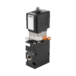
PN16

Burkert Type 8652 AirLINE valve island optimised for process automation. Features Industrial Ethernet, PROFINET S2, Hot Swap, and ATEX/IECEx Zone 2 approvals.
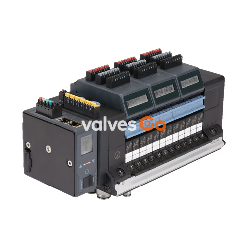
Burkert Type 8652 AirLINE valve island has been especially developed for process automation requirements. New diagnostic functions can be visualised on the LC display, both in clear text as well as symbols. This makes it easy to relate to the shown messages and helps to save time during start-up and maintenance. Furthermore, the diagnostic message is also available at the controller, enabling a fast overview of the plant status.
The hardware is optimised for installation at the bottom of the control cabinet. Installation on a standard rail is also possible. Key pneumatic functions ensure increased process reliability. For instance, check valves in the exhaust air ducts make sure there is no unplanned actuation due to pressure peaks.

Key Features:
| Product properties | Description |
|---|---|
| Material | Body: PA (polyamide) Seal: NBR and PUR |
| Width per station | 11 mm |
| Manual override | Latching, spring return (optional: lockable) |
| Number of valve slots | Max. 24 |
| Maximum valve functions | Max. 48 |
| Pneumatic intermediate supply | Optional for the variants with 16, 20 and 24 valve slots |
| Pressure range | Vac...10 bar (Overpressure to atmospheric pressure) |
| External supply air | 3...10 bar (auxiliary pilot air) |
| Flow rate QNn value air | 310 l/min (measured at +20 °C, 6 bar pressure at valve inlet and 1 bar differential pressure) |
| Flow rate with Hot Swap | Flow reduced by approx. 3% |
| Operating voltage | 24 V DC (±10% tolerance) |
| Nominal power of each valve | 0.7 W (0.175 W after power reduction) |
| Nominal current of each valve | 29 mA (10 mA after power reduction) |
| Digital input | Max. 48 |
| Operating medium | Oil-free or lubricated compressed dry air, neutral gases (5 μm filter recommended) |
| Compressed air quality | ISO 8573-1: 2010, Class 7.4.4 |
| Degree of protection | IP20, IP65 in closed control cabinets |
| Ambient temperature | -10 °C...+55 °C |
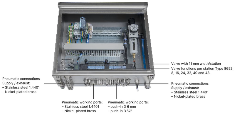
AirLINE Quick considerably reduces the use of components in the control cabinet. With the AirLINE Quick Adapter, the valve terminal is adapted directly to the control cabinet floor or control cabinet wall.
Advantages:
| AirLINE Quick Properties | Description |
|---|---|
| Adapter Plate Material | Stainless steel 1.4301 or Anodised aluminium |
| Pneumatic connection Material | Stainless steel 1.4401 or Nickel-plated brass |
| Valve functions per station | 8, 16, 24, 32, 40 and 48 |
| Pneumatic Supply / Exhaust | Push-in D 10 mm, 3/8" |
| Pneumatic working ports | Push-in D 6 mm, 1/4" |
| Approval | Description |
|---|---|
| Explosion protection | Optional: As a category 3 device suitable for zone 2/22. ATEX: BVS 20 ATEX E 031 U (II 3G Ex ec IIC Gc / II 3D Ex tc IIIC Dc) IECEx: IECEx BVS 20.0024 U (Ex ec IIC Gc / Ex tc IIIC Dc) |
| UL Listed (USA/Canada) | Optional: UL 61010-1, CAN/CSA-C22.2 No. 61010-1 |
| UL Recognized (Hazardous Locations) | Optional: Class I, Zone 2, AEx ec IIC Gc / Ex ec IIC Gc U Class II, Zone 22, AEx tc IIIC Dc / Ex tc IIIC Dc U Class I, Division 2, Group A, B, C, D / Class II, III, Division 2, Group F, G |
| CCC | Optional: China Compulsory Certification for hazardous applications in China. |
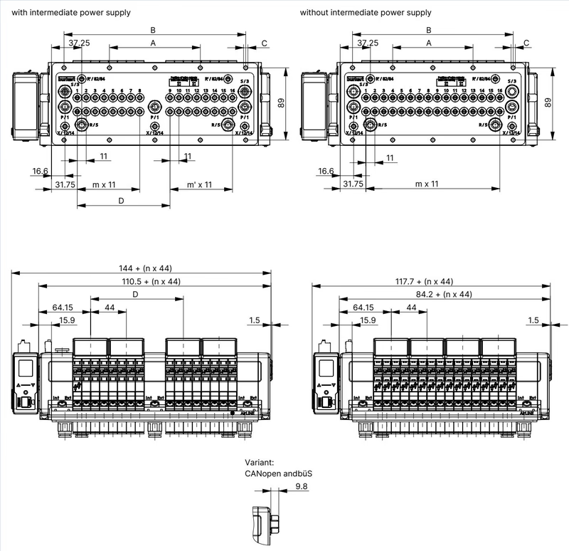
| Variant | A | B | C | m | n |
|---|---|---|---|---|---|
| 4-fold | 66 | - | 4 x M5 | 3 | 1 |
| 8-fold | 35 | 111 | 8 x M5 | 7 | 2 |
| 12-fold | 77 | 154 | 10 x M5 | 11 | 3 |
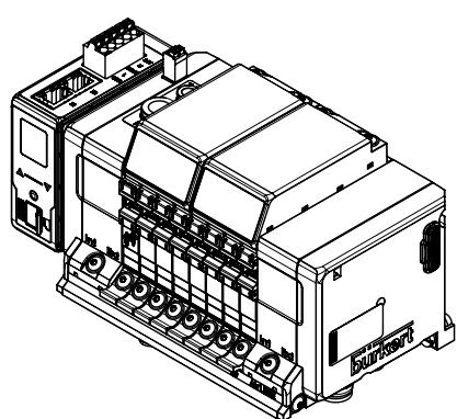
| Variant | A | B | C | D | m | m' | n |
|---|---|---|---|---|---|---|---|
| 16-fold with intermediate supply | 112 | 224 | 10 x M5 | 114.3 | 7 | 7 | 4 |
| 20-fold with intermediate supply | 134 | 268 | 10 x M5 | 158.3 | 11 | 7 | 5 |
| 24-fold with intermediate supply | 156 | 312 | 10 x M5 | 158.3 | 11 | 11 | 6 |
| 16-fold without intermediate supply | 99 | 198 | 10 x M5 | - | 15 | - | 4 |
| 20-fold without intermediate supply | 121 | 242 | 10 x M5 | - | 19 | - | 5 |
| 24-fold without intermediate supply | 143 | 286 | 10 x M5 | - | 23 | - | 6 |
Connect 5-pin spring-loaded terminal according to the pin assignment (Possible cable cross-section: ≤ 1.5 mm²).
| Pin | Colour | Assignment |
|---|---|---|
| 1 | Red | 24 V DC |
| 2 | White | CAN_H (büS connection) |
| 3 | Green | SHIELDING |
| 4 | Blue | CAN_L (büS connection) |
| 5 | Black | GND |
The interface plate has a 2-pin spring-loaded terminal to which the pneumatic valves’ power supply is connected.
| Clip | Colour | Assignment |
|---|---|---|
| 1 | Red | AUX 24 V |
| 2 | Black | GND |
Industrial Ethernet (PROFINET IO, EtherNet/IP, Modbus TCP, EtherCAT, CC-Link IE Field Basic) or PROFINET S2 – Interface X1 and X2 RJ45
| Pin | Assignment |
|---|---|
| 1 | TX+ |
| 2 | TX- |
| 3 | RX+ |
| 4 | N.C. |
| 5 | N.C. |
| 6 | RX- |
| 7 | N.C. |
| 8 | N.C. |
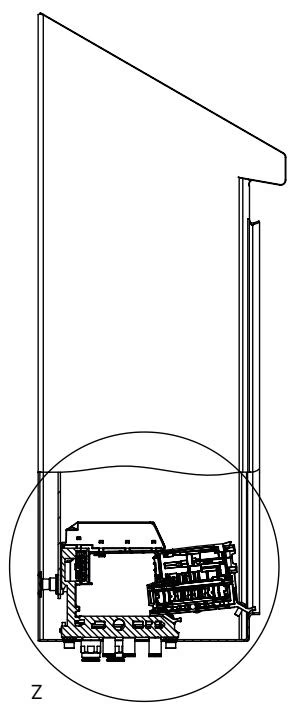
To use the Hot Swap function, always observe a minimum distance to the front edge of the control cabinet when installing the valve island inside the control cabinet.
The digital inputs are supplied (24 V) by the electronic module. Current is limited to maximum 30 mA per digital input. Standard 3-wire sensors and 2-wire sensors with voltages between 10…30 V as well as mechanical limit switches can be used.
| Possible data | 3-wire sensors | 2-wire sensors | Mechanical limit switches |
|---|---|---|---|
| Sensor actuated | X | X | X |
| Sensor not actuated | X | X | X |
| Short circuit | X | - | - |
| Wire break | - | X | - |
Type 6534 valves are equipped with additional connection terminals. A valve circuit can therefore be interrupted by an external switch. Manual override is not required for these valve variants. To use the shut-off function, connect the terminal to a potential-free contact (mechanical switch or relay).
Optional connections for module-based safety shutdown: Terminal 1 = valve unit 1, Terminal 2 = valve unit 2, etc. To use the switch-off function, connect the connection to a potential-free contact.
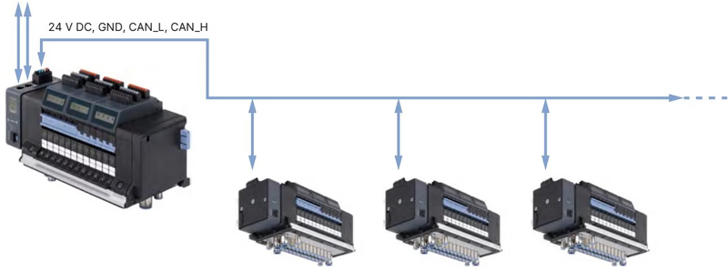
The following illustration shows a network with the example of AirLINE Type 8652 with Industrial Ethernet variant as master valve terminal and various AirLINE Type 8652 with büS variant as slave valve terminals.
DANGER CAUSED BY VOLTAGE
DANGER OF EXPLOSION CAUSED BY ELECTROSTATIC CHARGE
SPECIAL CONDITIONS FOR SAFE USE
Explore similar products in our catalog