


PN25

BURKERT 20112410 Type 2921 is a manually operated 2/2-way globe valve with DN 25 DIN EN 1092-1 PN25 flange connection, stainless steel 316L body, PEEK seat seal, PPS handwheel, and 13 m³/h flow capacity.
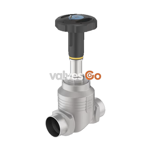
BURKERT 20112410 (Type 2921) is a manually operated 2/2-way globe valve designed for shutting off neutral and aggressive fluids, gases, and steam. Built with a cast stainless steel 316L (CF3M) valve body and an integrated manual actuator, the valve uses a swivel plate closure member that seals against the fluid stream with flow directed below the valve seat. For this specific article number, the port connection is a DN 25 flange according to DIN EN 1092-1 PN 25, paired with a PEEK soft seat seal and a 45 mm diameter polyphenylene sulphide (PPS) handwheel. The valve delivers a nominal water flow coefficient Kv of 13.0 m³/h (Cv 15.1 gpm) and handles operating pressures from 0 bar(g) up to 25 bar(g).
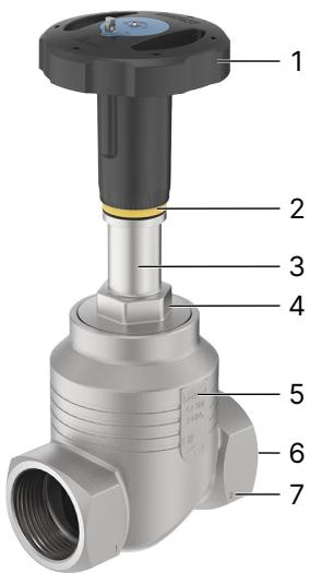
Flow Direction
The valve seat closes against the medium flow. Installation must direct flow beneath the valve seat (flow to open) as indicated by the cast direction arrow on the valve body.
Type 2921 covers port connection sizes from DN 10 to DN 100. The operational limits and fluidic data depend on the port connection size, the handwheel size, and the seat seal material.
| Connection Size DN | Connection Size NPS | Handwheel Diameter [mm] | Max. Operating Pressure (PTFE Seal) [bar(g)] | Max. Operating Pressure (PEEK Seal) [bar(g)] | Flow Coefficient Kv [m³/h] |
|---|---|---|---|---|---|
| 10 | 3/8 | 45 (S) | 25 | 25 | 4.7 |
| 15 | 1/2 | 45 (S) | 25 | 25 | 4.7 |
| 20 | 3/4 | 45 (S) | 25 | 25 | 8.1 |
| 25 | 1 | 45 (S) | 25 | 25 | 13.0 |
| 32 | 1 1/4 | 45 (S) | 25 | 25 | 20.0 |
| 40 | 1 1/2 | 45 (S) / 110 (M) | 25 | 25 | 31.0 |
| 50 | 2 | 110 (M) | 25 (20)* | 23 (20)* | 45.0 |
| 65 | 2 1/2 | 160 (L) | 24 (15)* | 14 | 73.0 |
| 80 | 3 | 160 (L) | 16 | 10 | 110.0 |
| 100 | 4 | 160 (L) | 10 | 6 | 165.0 |
*Note: Pressures in parentheses apply to compressible fluids of Group 1 (hazardous gases and vapors according to Directive 97/23/EC, Article 3 No. 1.3 letter a first dash). For DN 40, handwheel size S (45 mm) is limited to operating pressures below 16 bar.
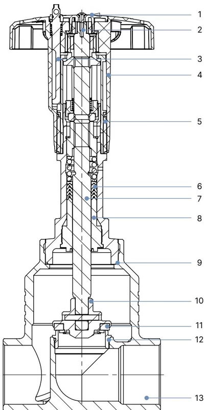
The internal assembly of Type 2921 utilizes corrosion-resistant metals and engineered polymers to maintain spindle tightness under high switching duty cycles.
| Item No. | Component | Material |
|---|---|---|
| 1 | Cover | Polyamide (PA) |
| 2 | Screw | Stainless steel 1.4301 |
| 3 | Locking device | Stainless steel 1.4305 |
| 4 | Handwheel | Polyphenylene sulphide (PPS) |
| 5 | Visual position indicator with scale | Polyamide (PA) |
| 6 | Packing gland | Filled PTFE V-rings, spring-compensated |
| 7 | Spindle | Stainless steel 1.4401 (316) / 1.4404 (316L) |
| 8 | Spindle guide | PEEK (DN 15 to DN 50); Stainless steel 1.4401/1.4404 (DN 65 to DN 100) |
| 9 | Housing seal | Graphite |
| 10 | Swivel plate | Stainless steel 1.4401 (316) / 1.4404 (316L) |
| 11 | Seat seal | PEEK (standard on 20112410) or PTFE |
| 12 | Valve seat with O-ring | Stainless steel 1.4571, EPDM |
| 13 | Valve body | Stainless steel 316L / CF3M |
The manual actuator is sized to balance torque requirements across port sizes. Size S (45 mm) features a thread pitch slope of 1.25 mm per revolution.
| Nominal Diameter DN | Nominal Diameter NPS | Handwheel Diameter [mm] | Height H1 [mm] | Height H2 with Locking [mm] |
|---|---|---|---|---|
| 15 | 1/2 | 45 (S) | 217 | 224 |
| 20 | 3/4 | 45 (S) | 224 | 230 |
| 25 | 1 | 45 (S) | 228 | 234 |
| 32 | 1 1/4 | 45 (S) | 296 | 303 |
| 40 | 1 1/2 | 45 (S) / 110 (M) | 301 | 307 |
| 50 | 2 | 110 (M) | 307 | 313 |
| 65 | 2 1/2 | 160 (L) | 361 | 368 |
| 80 | 3 | 160 (L) | 369 | 375 |
| 100 | 4 | 160 (L) | 379 | 385 |
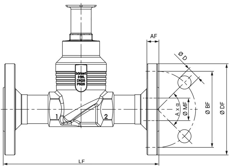
Article 20112410 features DIN EN 1092 PN 25 flange dimensions with face-to-face length according to DIN EN 558-1 Series 1.
| DN | DIN EN 1092 PN 25 FTF 1 (DIN EN 558-1) ∅DF [mm] | LF [mm] | ∅BF [mm] | AF [mm] | ∅D [mm] | Holes A x α | ∅MF [mm] | JIS 10K FTF 10 (DIN EN 558-2) ∅DF [mm] | LF [mm] | ∅BF [mm] | AF [mm] | ∅D [mm] | Holes A x α | ∅MF [mm] |
|---|---|---|---|---|---|---|---|---|---|---|---|---|---|---|
| 10 | 90 | 130 | 60 | 16 | 14 | 4 x 90° | 13.6 | — | — | — | — | — | — | — |
| 15 | 95 | 130 | 65 | 16 | 14 | 4 x 90° | 18.1 | 95 | 108 | 70 | 12 | 15 | 4 x 90° | 18.1 |
| 20 | 105 | 150 | 75 | 18 | 14 | 4 x 90° | 23.7 | 100 | 117 | 75 | 14 | 15 | 4 x 90° | 23.7 |
| 25 | 115 | 160 | 85 | 18 | 14 | 4 x 90° | 29.7 | 125 | 127 | 90 | 14 | 19 | 4 x 90° | 29.7 |
| 32 | 140 | 180 | 100 | 18 | 18 | 4 x 90° | 38.4 | 135 | 140 | 100 | 16 | 19 | 4 x 90° | 38.4 |
| 40 | 150 | 200 | 110 | 18 | 18 | 4 x 90° | 44.3 | 140 | 165 | 105 | 16 | 19 | 4 x 90° | 44.3 |
| 50 | 165 | 230 | 125 | 20 | 18 | 4 x 90° | 56.3 | 155 | 203 | 120 | 16 | 19 | 4 x 90° | 56.3 |
| 65 | 185 | 290 | 145 | 22 | 18 | 8 x 45° | 66.0 | 175 | 216 | 140 | 18 | 19 | 4 x 90° | 71.5 |
| 80 | 200 | 310 | 160 | 24 | 18 | 8 x 45° | 81.0 | 185 | 241 | 150 | 18 | 19 | 8 x 45° | 84.3 |
| 100 | 235 | 350 | 190 | 24 | 22 | 8 x 45° | 100.0 | 210 | 292 | 175 | 18 | 19 | 8 x 45° | 109.1 |
For systems designed to American standards, Type 2921 is also available with ANSI B16.5 Class 150 flanges (FTF 37 according to DIN EN 558-2):
| NPS | Flange ∅DF [mm] | Face-to-Face LF [mm] | Bolt Circle ∅BF [mm] | Flange Thickness AF [mm] | Bolt Hole ∅D [mm] | Holes A x α | Raised Face ∅MF [mm] |
|---|---|---|---|---|---|---|---|
| 1/2 | 89 | 184 | 60.5 | 11.2 | 15.7 | 4 x 90° | 15.7 |
| 3/4 | 99 | 184 | 69.9 | 12.7 | 15.7 | 4 x 90° | 20.8 |
| 1 | 108 | 184 | 79.2 | 14.2 | 15.7 | 4 x 90° | 26.7 |
| 1 1/2 | 127 | 222 | 98.6 | 17.5 | 15.7 | 4 x 90° | 40.9 |
| 2 | 152 | 254 | 120.7 | 19.1 | 19.1 | 4 x 90° | 52.6 |
| 2 1/2 | 178 | 276 | 139.7 | 22.3 | 19.1 | 4 x 90° | 62.7 |
| 3 | 190 | 298 | 152.5 | 23.9 | 19.1 | 4 x 90° | 78.0 |
| 4 | 229 | 352 | 190.5 | 23.9 | 19.1 | 8 x 45° | 102.4 |
Beyond flanged bodies, the Type 2921 family includes threaded connections (G, NPT, Rc per EN ISO 228-1, ASME B1.20.1, ISO 7-1), welded connections (EN ISO 1127/ISO 4200, DIN 11850-2, ASME BPE, SMS 3008), and clamp connections (DIN 32676 Series A/B, ASME BPE).
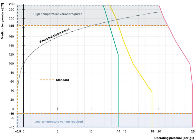
Maximum allowable working pressures decrease at elevated operating temperatures in accordance with the pressure rating standards.
| Temperature [°C] | DIN EN 12516-1 (PN 25) Max. Pressure [bar] | ASME B16.34 Cl. 150 Max. Pressure [bar] | JIS B 2220 10K Max. Pressure [bar] |
|---|---|---|---|
| -10 to +38 / +50 | 25.0 | 19.0 (at -29...+38 °C) / 18.4 (50 °C) | 14.0 |
| 100 | 24.5 | 16.2 | 14.0 |
| 150 | 22.4 | 14.8 | 13.4 |
| 200 | 20.3 | 13.7 | 12.4 |
| 230 | 19.0 | 12.7 | 11.7 |
Pressure Hazard
Depressurize pipelines and drain or vent all process fluids before installing, removing, or servicing the valve. Wear protective gloves when handling valves that operate with hot or corrosive media.
Body Connection Torque
When servicing or installing actuators on valve bodies, adhere strictly to the body connection tightening torques. Grease external body threads with Klüberpaste UH1 96-402 (or equivalent certified lubricant).
| Valve Body Nominal Diameter DN | Tightening Torque [Nm] | Tolerance [Nm] |
|---|---|---|
| 10 / 15 | 45 | ±3 |
| 20 | 50 | ±3 |
| 25 | 60 | ±3 |
| 32 | 65 | ±3 |
| 40 | 65 | ±3 |
| 50 | 70 | ±3 |
| 65 | 100 | ±3 |
| 80 | 120 | ±5 |
| 100 | 150 | ±5 |
High Vibration and High Temperature Notice
In installations subject to severe vibration or operating temperatures above 140 °C, check the body connection screw joint before startup and at periodic operational intervals.
Under normal service conditions, the manual actuator is maintenance-free. Conduct a visual inspection of the valve and check the actuator relief bore for fluid leakage at least once per year. Abrasive or particulate-laden media require shorter inspection intervals.
| Fault / Malfunction | Cause | Corrective Action |
|---|---|---|
| Valve does not seal tightly at seat | Particulates lodged between seal and seat | Install an upstream strainer / dirt trap |
| Seat seal worn or damaged | Replace the closure member / seal set | |
| Flow direction reversed | Correct piping so flow enters below the seat | |
| Operating pressure exceeds limit | Verify system pressure against type label limits | |
| Leakage at relief bore | Spindle packing gland worn | Replace the packing gland set |
Explore similar products in our catalog



