


PN25

BURKERT 20112527 (Type 2960) is a manually operated 2-way angle seat control valve with DN 15 welded ends, PN25 rating, equal percentage parabolic cone, PTFE seat seal, and 5.0 m³/h flow capacity.
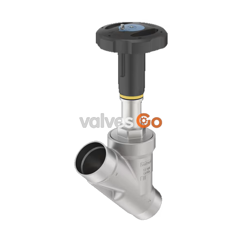
BURKERT 20112527 (Type 2960) is a manually operated 2-way angle seat control valve engineered for fine fluid throttling and continuous flow adjustment across liquid, gas, and steam installations. Constructed with a 316L/CF3M stainless steel cast body and DIN EN ISO 1127 / ISO 4200 / DIN 11866 series B butt-weld ends (outer diameter 21.3 mm, wall thickness 1.6 mm), this DN 15 (NPS 1/2) valve integrates a precision-contoured parabolic plug that delivers up to 35% higher flow throughput than standard globe control valves of equivalent nominal size.
The valve incorporates an equal-percentage flow profile with a 50:1 theoretical rangeability, operating with fluid entering beneath the seat to ensure smooth opening characteristics and stable seating. Sealing integrity is established by a soft PTFE seat seal providing bubble-tight shutoff conforming to DIN EN 60534-4 Leakage Class VI across operating pressures up to 25 bar(g). The manual assembly features a high-grade polyphenylene sulfide (PPS) handwheel (size S, 45 mm diameter) with an integrated optical indicator and calibrated stroke scale, paired with a spring-loaded PTFE V-ring stem packing gland that requires no manual retightening.
| Specification Parameter | Value |
|---|---|
| Valve Type | Manually operated 2-way angle seat control valve (Type 2960) |
| Article Number | 20112527 |
| Nominal Diameter | DN 15 (NPS 1/2) |
| Pipe Connection Standard | DIN EN ISO 1127 / ISO 4200 / DIN 11866 series B |
| Pipe Dimensions (Ø DS x WS) | 21.3 mm x 1.6 mm |
| Face-to-Face Dimension (LS) | 100 mm |
| Nominal Pressure Class | PN 25 (DIN EN 1333), Class 150 (DIN EN 1759) |
| Operating Pressure Range | 0 bar(g) to 25 bar(g) |
| Medium Temperature Range | -10 °C to +130 °C (PTFE seat seal limit) |
| Ambient Temperature Range | -10 °C to +60 °C |
| Flow Capacity (Kvs / Cv) | 5.0 m³/h / 5.8 gpm (measured with water per DIN EN 60534-2-4) |
| Seat Diameter | 15 mm (9/16") |
| Nominal Full Stroke | 14 mm |
| Flow Characteristic | Modified equal percentage (50:1 rangeability) |
| Leakage Class | DIN EN 60534-4 Class VI (PTFE soft seal) |
| Flow Direction | Below seat (flow to open) |
| Viscosity Handling | Up to 600 mm²/s |
| Conformities & Standards | Directive 2014/68/EU (PED), EC Regulation 1935/2004, FDA compliant wetted materials |
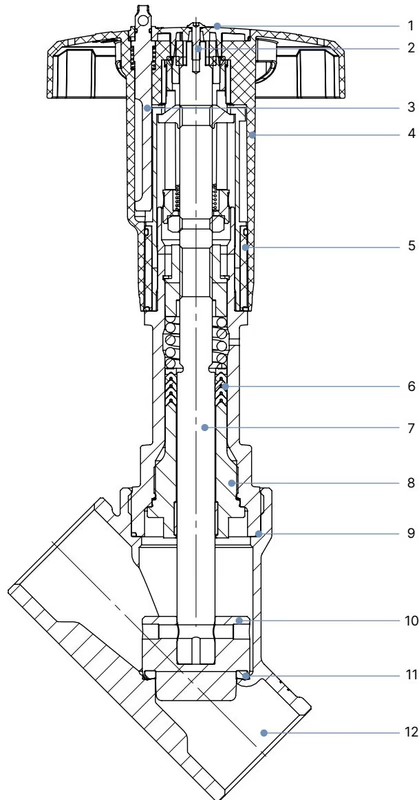
| Item No. | Component | Material |
|---|---|---|
| 1 | Cover | Polyamide (PA) |
| 2 | Fastening screw | Stainless steel 1.4301 |
| 3 | Lock pin (optional accessory) | Stainless steel 1.4305 |
| 4 | Handwheel | Polyphenylene sulfide (PPS) |
| 5 | Optical position indicator with scale | Polyamide (PA) |
| 6 | Stem packing gland | Filled PTFE V-rings with internal spring compensation |
| 7 | Spindle | Stainless steel 1.4401 / 1.4404 |
| 8 | Spindle guide | Stainless steel 1.4404 (316L), PTFE filled |
| 9 | Body gasket | Graphite |
| 10 | Control cone | Stainless steel 1.4571 |
| 11 | Seat seal | PTFE (Polytetrafluoroethylene) |
| 12 | Valve body | Cast stainless steel 316L / CF3M |
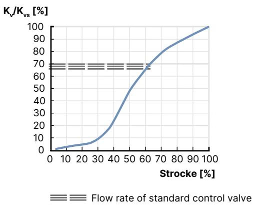
Type 2960 valves utilize an equal percentage parabolic control plug that delivers a modified equal percentage characteristic according to DIN EN 60534-2-4. The theoretical rangeability (Kvs / Kvo) is 50:1 for seat diameters from 8 mm to 100 mm. For seat sizes greater than 10 mm, the minimum controllable flow value (Kvr) is maintained at 5% of valve travel.
Flow enters beneath the seat, stabilizing the plug and eliminating water hammer during closing. The table below details the step-by-step flow capacity (Kv values in m³/h) across stroke percentages for DN 15:
| Nominal Size | Handwheel Ø | Max Operating Pressure (Leakage Class) | Kv at 5% Travel | Kv at 10% | Kv at 20% | Kv at 30% | Kv at 40% | Kv at 50% | Kv at 60% | Kv at 70% | Kv at 80% | Kv at 90% | Full Kvs |
|---|---|---|---|---|---|---|---|---|---|---|---|---|---|
| DN 15 (Standard) | 45 mm (S) | 25 bar(g) (Class VI) | 0.16 | 0.17 | 0.22 | 0.40 | 1.20 | 2.70 | 3.50 | 4.00 | 4.50 | 4.80 | 5.00 m³/h |
| DN 15 (ASME BPE) | 45 mm (S) | 25 bar(g) (Class VI) | 0.22 | 0.24 | 0.30 | 0.56 | 1.20 | 1.50 | 1.50 | 1.50 | 1.50 | 1.50 | 1.50 m³/h |
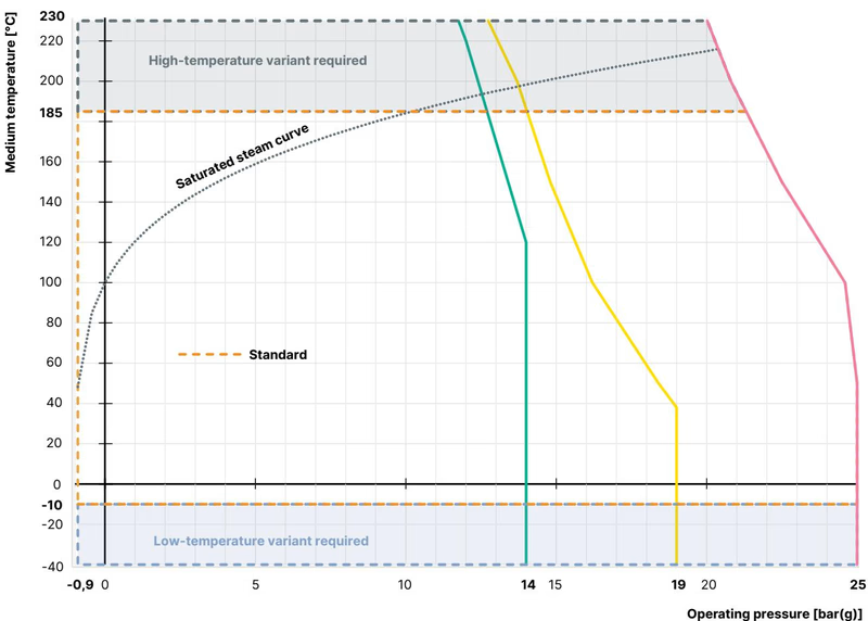
Maximum allowable working pressure decreases with increasing fluid temperature. The table below outlines pressure limitations according to DIN EN 12516-1 (PN 25) and ASME B16.34 (Class 150):
| Operating Temperature | PN 25 Body Rating (DIN EN 12516-1) | Class 150 Body Rating (ASME B16.34) | JIS 10K Rating (JIS B 2220) |
|---|---|---|---|
| -10 °C to +50 °C | 25.0 bar | 19.0 bar (from -29 °C) | 14.0 bar |
| +100 °C | 24.5 bar | 16.2 bar | 14.0 bar |
| +130 °C (Max for PTFE seat) | 23.2 bar | 15.3 bar | 13.6 bar |
| +150 °C | 22.4 bar | 14.8 bar | 13.4 bar |
| +200 °C | 20.3 bar | 13.7 bar | 12.4 bar |
| +230 °C | 19.0 bar | 12.7 bar | 11.7 bar |
Operating Temperature Restrictions
Article 20112527 is fitted with a soft PTFE seat seal rated for medium temperatures between -10 °C and +130 °C. For processes exceeding +130 °C (up to +230 °C), factory variants equipped with PEEK or stainless steel seats are required.
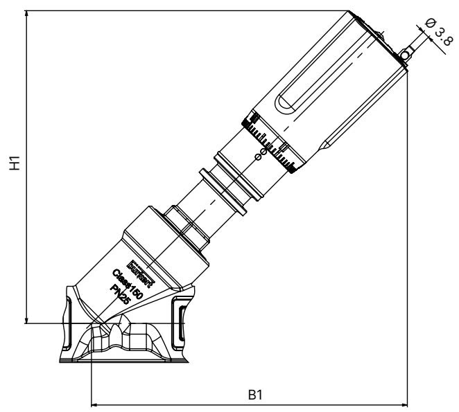
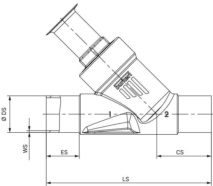
| Pipe Nominal Size (DN / NPS) | Handwheel Diameter (Ø) | Max Width B1 (mm) | Max Height H1 (mm) | Slope per Handwheel Revolution |
|---|---|---|---|---|
| DN 15 (NPS 1/2) | 45 mm (Size S) | 148 | 148 | 1.25 mm |
| DN 20 (NPS 3/4) | 45 mm (Size S) | 154 | 154 | 1.25 mm |
| DN 25 (NPS 1) | 45 mm (Size S) | 163 | 163 | 1.25 mm |
| DN 32 (NPS 1 1/4) | 110 mm (Size M) | 224 | 224 | 1.75 mm |
| DN 40 (NPS 1 1/2) | 110 mm (Size M) | 224 | 224 | 1.75 mm |
| DN 50 (NPS 2) | 110 mm (Size M) | 241 | 241 | 1.75 mm |
| DN 65 (NPS 2 1/2) | 160 mm (Size L) | 290 | 290 | 2.00 mm |
| Nominal Size (DN) | ES (Weld Depth) [mm] | CS (Center-to-Bottom) [mm] | LS (Face-to-Face) [mm] | Ø DS (Pipe OD) [mm] | WS (Wall Thickness) [mm] |
|---|---|---|---|---|---|
| DN 15 | 19 | 34 | 100 | 21.3 | 1.6 |
| DN 20 | 20 | 39 | 115 | 26.9 | 1.6 |
| DN 25 | 26 | 43 | 130 | 33.7 | 2.0 |
| DN 32 | 26 | 45 | 145 | 42.4 | 2.0 |
| DN 40 | 26 | 49 | 160 | 48.3 | 2.0 |
| DN 50 | 26 | 50 | 175 | 60.3 | 2.0 |
| DN 65 | 26 | 50 | 210 | 76.1 | 2.3 |
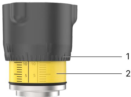
Rotating the handwheel counterclockwise lifts the spindle and opens the valve. Turning clockwise drives the plug toward the closed position. For Size S actuators (45 mm handwheel), spindle advance is 1.25 mm per full turn.
Installation on Welded Pipe Systems
Before welding the valve body into the line, the manual actuator must be separated from the body to protect the seals and internal guide from heat distortion:
| Valve Body Nominal Diameter | Tightening Torque [Nm] | Tolerance |
|---|---|---|
| DN 10 / DN 15 | 45 | ±3 Nm |
| DN 20 | 50 | ±3 Nm |
| DN 25 | 60 | ±3 Nm |
| DN 32 | 65 | ±3 Nm |
| DN 40 | 65 | ±3 Nm |
| DN 50 | 70 | ±3 Nm |
| DN 65 | 100 | ±3 Nm |
| Malfunction | Underlying Cause | Corrective Action |
|---|---|---|
| Valve does not seal tightly | Particulate contamination between plug and seat | Clean seating surface; install an upstream pipeline strainer |
| PTFE seat seal worn or damaged | Replace the plug closure member | |
| Reverse pipeline flow | Reinstall valve matching the flow direction arrow (below seat) | |
| Line pressure exceeds limit | Verify pipeline pressure against type label limits (max 25 bar) | |
| External leakage at relief bore | Spindle packing gland worn | Replace the PTFE V-ring stem packing set |
Explore similar products in our catalog



