

PN16

BURKERT 20114064 Type 8647 AirLINE SP is an 8-bank electro-pneumatic valve island for Siemens SIMATIC ET 200SP/SP HA featuring 11 mm station width, integrated pressure sensor, HotSwap, and ATEX/IECEx Zone 2 approval.
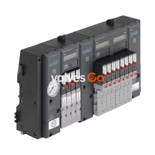
BURKERT 20114064 Type 8647 AirLINE SP is a modular electro-pneumatic valve island engineered for direct integration into Siemens SIMATIC ET 200SP and SIMATIC ET 200SP HA distributed I/O systems. This specific assembly features an 8-bank layout accommodating 8 valve stations at an 11.00 mm station width, utilizing a mixed valve population with 3/2-way valve functionality. The operating pressure spans from 2.50 bar to 10.00 bar, with an allowable medium temperature of 0.00 °C to 50.00 °C and an ambient operating temperature of 0.00 °C to 55.00 °C.
Constructed according to Revision 2 (REV.2) specifications, the assembly incorporates an integrated electronic pressure sensor providing analog pressure values via the fieldbus, a pneumatic HotSwap function via channel 1 (P) shutoff, and integrated non-return check valves in exhaust ducts 3 (R) and 5 (S). Certified under ATEX and IECEx for Category II 3 G Ex ec IIC T4 Gc, the system is designed for cabinet mounting with an IP20 ingress protection rating.
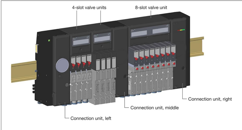
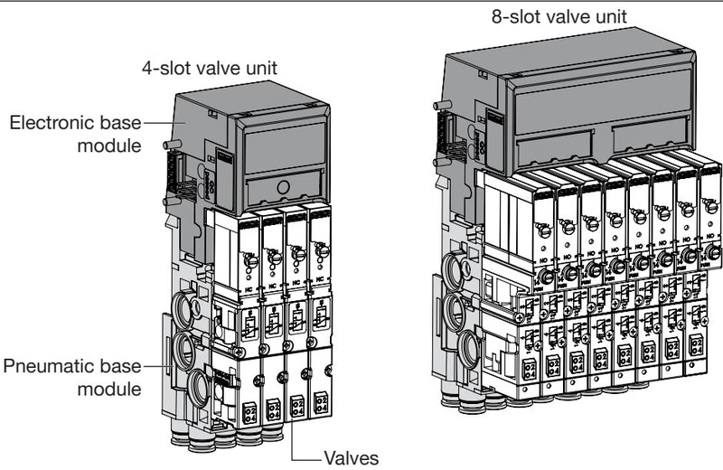
AirLINE SP Type 8647 acts as an electro-pneumatic sub-system that mechanically connects and electrically communicates with adjacent Siemens modules along a shared DIN standard rail. The valve island consists of supply connection units, pneumatic base modules, electronic base modules (PQ modules), and integrated pilot solenoid valves.
Connection units anchor the valve block to the standard rail, supply primary compressed air, and route exhaust air. Configuration 20114064 includes one integrated electronic pressure sensor module (PSU-L-PS or PSU-R-PS):
The 8-bank assembly utilizes electronic and pneumatic base units designed for station widths of 11 mm:
Revision 2 (REV.2) Design Standard
In Revision 2 hardware, single valves (Type 6524 3/2-way, Type 6525 5/2-way) and double valves (Type 6524 2x3/2-way) share a standardized FM20 flange interface. Single valves from REV.1 (FM14 flange) cannot be mounted onto REV.2 pneumatic base modules.
| Parameter | Technical Value |
|---|---|
| Product Identifier (SKU) | 20114064 |
| Device Type Family | AirLINE SP Type 8647 |
| Generation / Hardware State | Revision 2 (REV.2) |
| Valve Slot Count | 8 slots (8-bank) |
| Width per Station | 11.00 mm |
| Valve Function | Mixed valve population (3/2-way configuration) |
| Operating Medium | Compressed air oiled or unoiled, neutral gases (ISO 8573-1: 2010, Class 7.4.4) |
| Nominal Operating Pressure | 2.50 bar to 10.00 bar |
| Pressure Sensor Measuring Range | 0 to 10 bar (overpressure resistance up to 14 bar) |
| Medium Temperature Range | 0.00 °C to +50.00 °C |
| Permissible Ambient Temperature | 0.00 °C to +55.00 °C |
| Storage Temperature Range | -20.00 °C to +60.00 °C |
| Relative Humidity | 75% average, 85% occasionally (non-condensing) |
| Explosion Protection Rating | II 3 G Ex ec IIC T4 Gc / Ex ec IIC T4 Gc (ATEX, IECEx) |
| Ingress Protection Class | IP20 (verified according to EN 60529) |
| Housing Materials | PA, PC (Valves: PA, PPS, Aluminum; Seals: NBR) |
| Operating Voltage | 24 V DC (±10% SELV/PELV, max. ripple 2.4 Vss) |
| Load Voltage Bus Current | Up to 3 A maximum depending on activation load |
| Solenoid Power Consumption | 0.8 W per single coil (Type 6524 / 6525) |
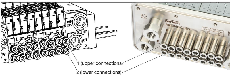
Primary air supply and deaeration occur through G 1/4 female thread connections located on the connection units. Actuator air delivery routes through push-in couplings located on the underside of the pneumatic base module.
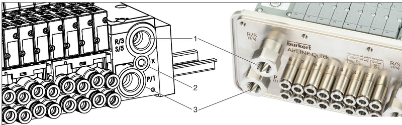
| Position | Port Identification | Port Function | Connection Dimension |
|---|---|---|---|
| 1 | R/3, S/5 | Common exhaust air | G 1/4 female thread |
| 2 | X | Auxiliary pilot air / pilot exhaust | M5 thread |
| 3 | P/1 | Primary pressure supply | G 1/4 female thread |
| Working Ports | 2, 4 | Working outputs to pneumatic actuators | Push-in coupling D6 (bottom) |
Configuration 20114064 includes integrated check valves in exhaust ducts 3 (R) and 5 (S), which stop back pressure from migrating into non-actuated lines during simultaneous switching or safety venting. The integrated channel 1 (P) shutoff mechanism enables valve replacement under continuous line pressure: when removing a pilot valve, an internal shutoff valve seals the primary pressure line, dropping leakage to a minimal level and preserving full operational pressure across neighboring valve stations. In REV.2, nominal flow reduction through the P-shutoff channel is limited to approximately 20% (compared to 50% in older REV.1 blocks).
AirLINE SP Type 8647 interfaces electrically via the internal backplane bus and power rail of the Siemens SIMATIC ET 200SP or ET 200SP HA base units. Power consumption from the 24 V DC load bus is monitored constantly. If supply voltage drops below 21.6 V (24 V - 10%), the PWR OK LED on connection module PSU-L extinguishes, output channels are shut down to prevent unstable valve states, and a "No supply voltage" diagnostic alert is dispatched.
Integration into automation architectures is supported through:
Pneumatics (Burkert)) and PROFIBUS DP masters.Each channel provides independent switching cycle counters for both the pilot solenoid valve and the field actuator. Data record DS 130 provides read-only cycle data for pilot valves, while DS 131 tracks actuator movements. Reset operations are executed over acyclic communication via data record DS 132. Service dates can be recorded in DS 133 (last maintenance) and DS 134 (next maintenance) using BCD notation.
EVS Circuit Isolation
When utilizing base modules with External Valve Shutdown (EVS), connect each EVS terminal solely to a potential-free contact such as a relay output. Never apply external voltage to EVS terminals, and never parallel several EVS terminals across different modules, as cross-coupling creates severe failure hazards.
Installation requires mounting onto a grounded DIN rail (profile rail for ET 200SP HA). The valve block is delivered fully assembled and secured with transportation screws that must be released before cabinet installation.
Installation Clearance
Maintain a minimum clearance of 5 cm between the top edge of the valve block and any overhead cabinet obstruction to allow heat dissipation and rail disengagement. If electronic base modules equipped with top-mounted EVS terminals are installed, increase clearance to at least 8 cm.
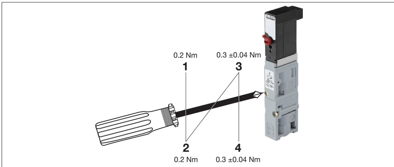
Thanks to the integrated P shutoff mechanism, solenoid valves can be serviced without depressurizing the main air header:
Explore similar products in our catalog


