PN25

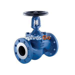
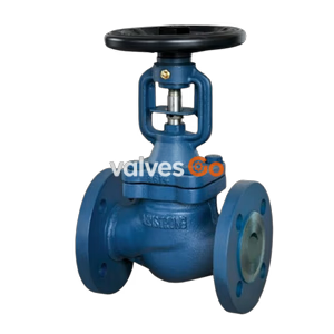
Burkert 20114631 Type 2921 manually operated 2/2-way globe valve. Features DN 80 flange connection, stainless steel body, and PTFE/PEEK seals. Suitable for media temperatures from -10°C to 230°C.
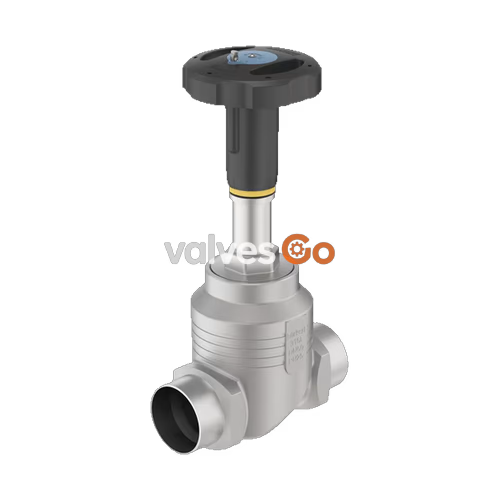
Burkert 20114631 Type 2921 globe valve consists of a manual actuator and a 2-way body made of stainless steel. With a high-quality valve body, the manually operated valve offers diverse usage options to shut off both neutral and aggressive gaseous and liquid media. The tried-and-tested self-adjusting packing gland guarantees optimal tightness and therefore enables low-maintenance operation, even at high switching cycles. Depending on the application, the soft PTFE or PEEK seal ensures a reliable valve seat seal, even under challenging operating conditions. The actuator is made of high-quality plastic and is suitable for use in demanding environments. It possesses a visual position indicator and can be optionally equipped with stroke limitation and locking.
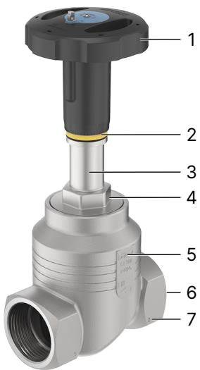
| Product properties | |
|---|---|
| Design | Globe valve on/off |
| Nominal diameter | DN 10...DN 100, NPS 3/8...NPS 4 |
| Flow direction | Flow to open (below seat) |
| Performance data | |
|---|---|
| Operating pressure | 0 bar(g)...25 bar(g) |
| Nominal pressure | PN 25 (DIN EN 1333), Class 150 (DIN EN 1759) |
| Seat leakage | Leakage rate A (DIN EN 12266-1), seat seal PTFE and PEEK, test medium air |
| Kv value | 0.1 m³/h...140 m³/h |
| Medium data | |
|---|---|
| Operating medium | Steam, water, neutral gases, alcohols, oils, fuels, hydraulic fluids, salt solutions, alkalis, organic solvents |
| Medium temperature | -40 °C...+230 °C |
| Viscosity | Max. 600 mm²/s |
| Environment and installation | |
|---|---|
| Environmental factors | Protect the device from electromagnetic interference, UV radiation and, when used outdoors, from weather conditions. |
| Ambient temperature | -10 °C...+60 °C |
| Installation position | As required, preferably with actuator upright |
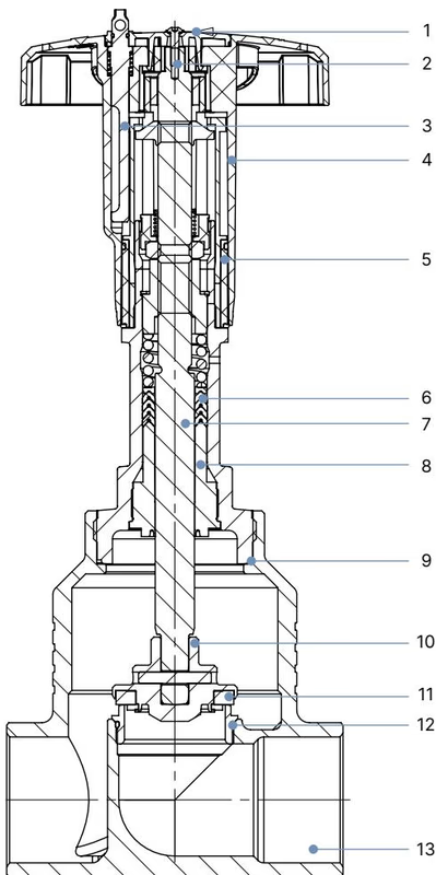
| No. | Element | Material |
|---|---|---|
| 1 | Cover | Polyamide (PA) |
| 2 | Screw | Stainless steel 1.4301 |
| 3 | Locking device | Stainless steel 1.4305 |
| 4 | Handwheel | Polyphenylene sulphide (PPS) |
| 5 | Visual position indicator with scale | Polyamide (PA) |
| 6 | Packing gland | PTFE V-rings (filled), with spring compensation |
| 7 | Spindle | Stainless steel 1.4401 (316)/1.4404 (316L) |
| 8 | Spindle guide | DN 15...DN 50: PEEK DN 65...DN 100: Stainless steel 1.4401 (316)/1.4404 (316L) |
| 9 | Housing seal | Graphite |
| 10 | Swivel plate | Stainless steel 1.4401 (316)/1.4404 (316L) |
| 11 | Seat seal | PTFE or PEEK |
| 12 | Valve seat with O-ring | Stainless steel 1.4571, EPDM |
| 13 | Valve body | Stainless steel 316L/CF3M |
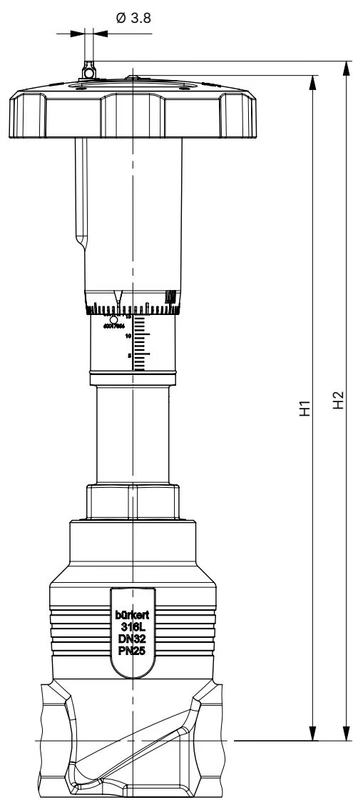
| DN | NPS | Handwheel diameter ∅ [mm] | H1 | H2 (locking) |
|---|---|---|---|---|
| 15 | 1/2 | 45 (S) | 217 | 224 |
| 20 | 3/4 | 45 (S) | 224 | 230 |
| 25 | 1 | 45 (S) | 228 | 234 |
| 32 | 1 1/4 | 45 (S) | 296 | 303 |
| 40 | 1 1/2 | 45 (S), 110 (M) | 301 | 307 |
| 50 | 2 | 110 (M) | 307 | 313 |
| 65 | 2 1/2 | 160 (L) | 361 | 368 |
| 80 | 3 | 160 (L) | 369 | 375 |
| 100 | 4 | 160 (L) | 379 | 385 |
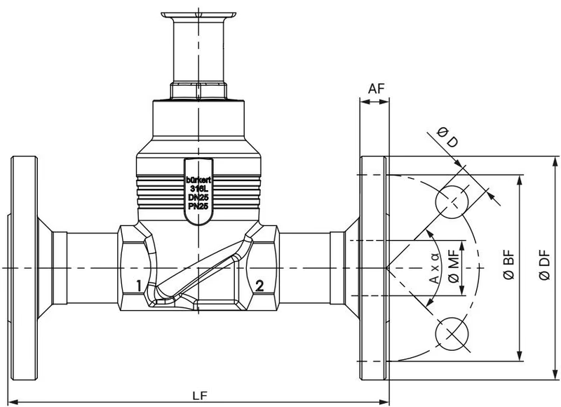
| DN | ∅ DF | LF | ∅ BF | AF | ∅ D | A x α | ∅ MF |
|---|---|---|---|---|---|---|---|
| 15 | 95 | 130 | 65 | 16 | 14 | 4 x 90° | 18.1 |
| 20 | 105 | 150 | 75 | 18 | 14 | 4 x 90° | 23.7 |
| 25 | 115 | 160 | 85 | 18 | 14 | 4 x 90° | 29.7 |
| 32 | 140 | 180 | 100 | 18 | 18 | 4 x 90° | 38.4 |
| 40 | 150 | 200 | 110 | 18 | 18 | 4 x 90° | 44.3 |
| 50 | 165 | 230 | 125 | 20 | 18 | 4 x 90° | 56.3 |
| 65 | 185 | 290 | 145 | 22 | 18 | 8 x 45° | 66.0 |
| 80 | 200 | 310 | 160 | 24 | 18 | 8 x 45° | 81.0 |
| 100 | 235 | 350 | 190 | 24 | 22 | 8 x 45° | 100.0 |
(Dimensions in mm for DIN EN 1092 PN 25 FTF 1 according to DIN EN 558-1)
Overview of fluidic data for flow below seat (for liquids, steam and gases):
| DN | NPS | Handwheel diameter ∅ [mm] | Operating pressure max. PTFE [bar(g)] | Operating pressure max. PEEK [bar(g)] | Kv value [m³/h] |
|---|---|---|---|---|---|
| 15 | 1/2 | 45 (S) | 25 | 25 | 4.7 |
| 20 | 3/4 | 45 (S) | 25 | 25 | 8.1 |
| 25 | 1 | 45 (S) | 25 | 25 | 13.0 |
| 32 | 1 1/4 | 45 (S) | 25 | 25 | 20 |
| 40 | 1 1/2 | 45 (S), 110 (M) | 25 | 25 | 31 |
| 50 | 2 | 110 (M) | 25 (20) | 23 (20) | 45 |
| 65 | 2 1/2 | 160 (L) | 24 (15) | 14 | 73 |
| 80 | 3 | 160 (L) | 16 | 10 | 110 |
| 100 | 4 | 160 (L) | 10 | 6 | 165 |
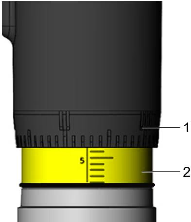
When turning the handwheel anticlockwise, the reproducible stroke scale becomes visible between the position indicator and the handwheel. The scale on the handwheel determines the rotation position of the handwheel (50 positions). The reproducible stroke scale shows, depending on the bottom edge of the handwheel, the relative position of the valve (valve opening) and acts as a fixation point for determining the rotation position.
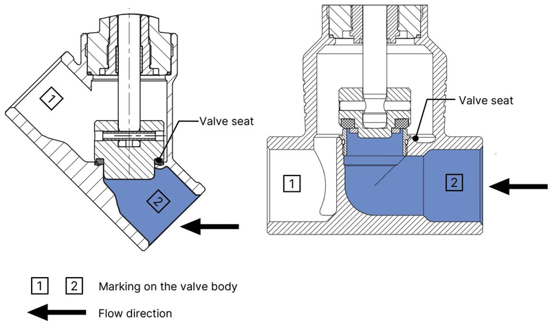
The valve seat is always closed against the medium flow. The flow direction should therefore be set such that the valve reaches the flow beneath the valve seat.
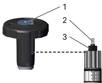
Setting the minimum and maximum stroke limit is possible as an option. An adjusting sleeve is used for this purpose.
It is also an option to lock the handwheel to prevent unintentional or unauthorised operation of the valve.
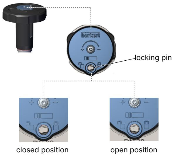
Push locking pin down and rotate by 180° (either clockwise or anticlockwise). The locking pin must lock into its end position so that the drill hole is fully visible once again. Insert padlock through the bore in the locking pin and secure.
DANGER!
Risk of injury due to high pressure and escaping medium.
WARNING!
Risk of injury due to improper installation.
| Fault | Cause | Elimination |
|---|---|---|
| Valve is not tight | Dirt between seal and valve seat | Install dirt trap |
| Valve seat seal worn | Install new control cone | |
| Flow direction interchanged | Observe the marking for the flow direction on the valve body | |
| Operating pressure too high | Observe pressure specifications on the type label | |
| Valve is leaking on the relief bore | Packing gland worn | Replacing packing gland |
Explore similar products in our catalog