


PN25

BURKERT 20121849 (Type 2100) is a pneumatically operated 2/2-way angle seat valve with DN20 PN25 flange connection, normally closed (NC) control function, PTFE seat seal, and flow rate Kv 11 m³/h up to 25 bar.
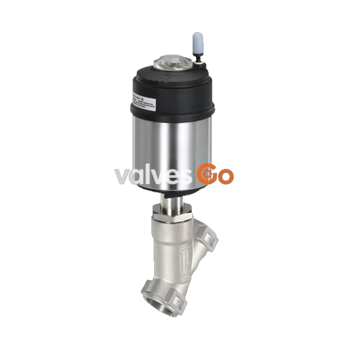
BURKERT 20121849 (Type 2100) is a pneumatically operated 2/2-way angle seat valve engineered for decentralized process automation. Equipped with a DN 20 flange connection according to DIN EN 1092-1 (pressure rating PN 25 and ASME Class 150) and a standard face-to-face installation length of 220 mm, the unit is configured in Control Function A (normally closed by internal spring force). Operating with flow below the seat, the valve delivers a water flow coefficient Kv of 11 m³/h and reliably seals operating media pressures up to 25 bar(g) with a minimum pilot pressure of 4.8 bar(g).

The flow-optimized CF3M stainless steel body houses a swivel plate with a virgin PTFE seat seal, achieving seat leakage rate A in accordance with DIN EN 12266-1 under air test media. Spindle sealing is maintained by a self-adjusting PTFE V-ring packing gland with integrated spring compensation. The pneumatic actuator comprises a 70 mm (size M) piston mechanism encased in 1.4561 (316Ti) stainless steel with a polyphenylene sulphide (PPS) cover, featuring integrated internal pilot air ducting and protection ratings of IP65/67 and NEMA Type 4X. Lubricants applied to the packing gland and actuator mechanism meet NSF H1 food-grade standards, and all wetted contact materials comply with European Regulation (EC) 1935/2004.
Burkert 20121849 operates according to Control Function A (CFA), functioning as a 2/2-way shut-off valve that is closed by mechanical spring force in its unpressurized rest position. Pressurizing pilot air port 1 lifts the piston and spindle against the return spring, retracting the swivel plate from the valve seat to allow media flow.
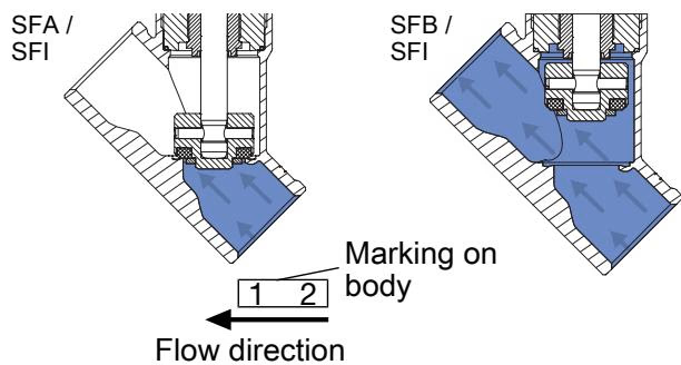
The valve utilizes flow direction below the seat (flow-to-open). Because media pressure acts directly beneath the swivel plate, line pressure assists in lifting the plug during opening. This geometry ensures smooth, gradual closing against the incoming fluid stream, preventing hydraulic water hammer shock in liquid circuits.
Water Hammer Hazard on Flow Above Seat
Valves engineered with flow direction above the seat must never be deployed for liquid media. In liquid circuits, closing with flow direction above the seat generates severe hydraulic shock loads (water hammer) that can rupture process pipework and valve bodies.
Every structural component of Burkert Type 2100 is engineered for aggressive process environments and CIP/SIP cleaning cycles:
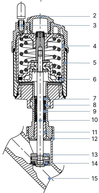
| No. | Component | Standard Material |
|---|---|---|
| 1 | Ground terminal | Stainless steel 1.4301 / 1.4305 (included on ATEX variants) |
| 2 | Optical position indicator | Polysulfone (PSU) |
| 3 | Pilot air ports | Polypropylene (PP) push-in connector (G 1/8 stainless steel 1.4305 on request) |
| 4 | Actuator cover | Polyphenylene sulphide (PPS) |
| 5 | Actuator casing | Stainless steel 1.4561 (316Ti) |
| 6 | Piston seal | Fluoroelastomer (FKM) |
| 7 | Return spring | Stainless steel 1.4310 |
| 8 | Tube / Actuator insert | Stainless steel 1.4401 (316) / 1.4404 (316L) |
| 9 | Packing gland | Filled PTFE V-rings with spring compensation |
| 10 | Valve spindle | Stainless steel 1.4401 (316) / 1.4404 (316L) |
| 11 | Spindle guide | Polyether ether ketone (PEEK) |
| 12 | Body seal | Graphite (PTFE optional) |
| 13 | Swivel plate | Stainless steel 1.4401 (316) / 1.4404 (316L) |
| 14 | Seat seal | Virgin PTFE (PEEK optional) |
| 15 | Valve body | Stainless steel CF3M |
Hygienic Lubrication & Food Contact
Lubricants applied within the actuator cylinder and the packing gland assembly comply with NSF H1 certification. Wetted materials satisfy the food-contact requirements of Regulation (EC) 1935/2004 according to manufacturer declarations.
For Burkert 20121849 (DN 20 seat, actuator size 70 mm / M, CF A), the minimum pilot pressure required to switch against full differential line pressure is 4.8 bar(g). The table below outlines fluidic operating limits across the welded and DIN EN 1092-1 flanged series with flow below the seat:
| Pipe OD [mm] | Nominal Diameter | Seat Size DN | Actuator Size Ø [mm] | Kv Value Water [m³/h] | Min. Pilot Pressure [bar(g)] | Max. Operating Pressure CF A (PTFE) [bar(g)] | Max. Operating Pressure CF A (PEEK) [bar(g)] | Max. Operating Pressure CF B (PTFE) [bar(g)] |
|---|---|---|---|---|---|---|---|---|
| 13.5 | DN 8 | 15 | 50 (D) | 2.6 | 5.2 | 25 | 25 | 25 |
| 13.5 | DN 8 | 15 | 70 (M) | 2.6 | 4.8 | 25 | 25 | 25 |
| 17.2 | DN 10 | 15 | 50 (D) | 5.3 | 5.2 | 25 | 25 | 25 |
| 17.2 | DN 10 | 15 | 70 (M) | 5.4 | 4.8 | 25 | 25 | 25 |
| 21.3 | DN 15 | 15 | 50 (D) | 5.3 | 5.2 | 25 | 25 | 25 |
| 21.3 | DN 15 | 15 | 70 (M) | 5.4 | 4.8 | 25 | 25 | 25 |
| 26.9 | DN 20 | 20 | 50 (D) | 10 | 5.2 | 16 | 13.5 | 25 |
| 26.9 | DN 20 (20121849) | 20 | 70 (M) | 11 | 4.8 | 25 | 25 | 25 |
| 33.7 | DN 25 | 25 | 50 (D) | 15 | 5.2 | 9 | — | 25 |
| 33.7 | DN 25 | 25 | 70 (M) | 20 | 4.8 | 16 | 13.5 | 25 |
| 33.7 | DN 25 | 25 | 90 (N) | 21 | 5.0 | 25 | 25 | 25 |
| 42.4 | DN 32 | 32 | 70 (M) | 26 | 4.8 | 8.5 | — | 25 |
| 42.4 | DN 32 | 32 | 90 (N) | 28 | 5.0 | 25 | 19.5 | 25 |
| 42.4 | DN 32 | 32 | 130 (P) | 30 | 5.0 | — | 25 | — |
| 48.3 | DN 40 | 40 | 70 (M) | 40 | 4.8 | 6 | — | 25 |
| 48.3 | DN 40 | 40 | 90 (N) | 44 | 5.0 | 16 | 13.5 | 25 |
| 48.3 | DN 40 | 40 | 130 (P) | 47 | 5.0 | 25 | 23 | 25 |
| 60.3 | DN 50 | 50 | 70 (M) | 49 | 4.8 | 4 | — | 16 |
| 60.3 | DN 50 | 50 | 90 (N) | 55 | 5.0 | 10 | 8 | 25 (20) |
| 60.3 | DN 50 | 50 | 130 (P) | 60 | 5.0 | 25 (20) | 23 (20) | 25 (20) |
| 76.1 | DN 65 | 65 | 90 (N) | 91 | 5.0 | 5 | — | 14 |
| 76.1 | DN 65 | 65 | 130 (P) | 91 | 5.6 | 16 (15) | 12.5 | 16 (15) |
| 88.9 | DN 80 | 80 | 130 (P) | 140 | 5.6 | 10 | 8 | 11 |
Note: Operating pressures in parentheses apply to compressible fluids of Group 1 in accordance with the Pressure Equipment Directive 2014/68/EU.
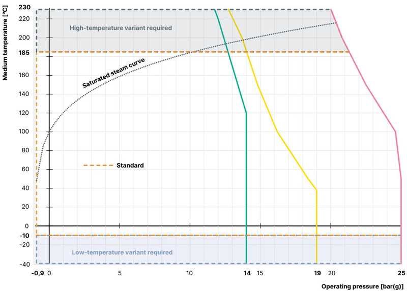
Operating pressures are constrained both by differential sealing capability and standard-specific pressure-temperature derating curves:
| Temperature [°C] | DIN EN 12516-1 / PN25 [bar] | ASME B16.34 Class 150 [bar] | JIS B 2220 10K [bar] |
|---|---|---|---|
| -10 to +50 (-29 to +38 for ASME) | 25.0 | 19.0 | 14.0 |
| 100 | 24.5 | 16.2 | 14.0 |
| 150 | 22.4 | 14.8 | 13.4 |
| 200 | 20.3 | 13.7 | 12.4 |
| 230 | 19.0 | 12.7 | 11.7 |
Ambient thermal thresholds depend on the pilot port connection style. Units fitted with standard 6 mm push-in air connectors are rated for ambient temperatures between -10 °C and +60 °C across medium temperatures from -10 °C to +230 °C. Fitting threaded G 1/8 metal bushings extends maximum permissible ambient temperature to +100 °C.
The valve may be installed in any orientation, though positioning the actuator vertically upright is recommended to minimize particulate deposition on the spindle seals.
When servicing the seat or dismantling the actuator from the valve body, the valve must be held in the open position to prevent mechanical damage to the swivel plate and seat sealing surfaces. For Control Function A units, 5.0 bar pneumatic pressure must be applied to pilot port 1 prior to loosening the body connection nut.
Tightening Torques for Body Connections
When assembling the actuator to the valve body, apply Klüberpaste UH1 96-402 grease to the interface threads and tighten to the specified nominal torque values:
The actuator housing can be rotated through 360° to align pilot air ports with plant pneumatic lines. While pilot pressure of 5.0 bar is maintained on port 1 to keep the valve open, an open-end wrench is positioned on the drive connection nut, holding the body connection fixed, and rotated in the specified clockwise orientation.
Routine maintenance involves visual checks at three key locations: media line connections, the relief bore on the actuator neck (indicating packing gland integrity), and the valve seat shut-off seal.
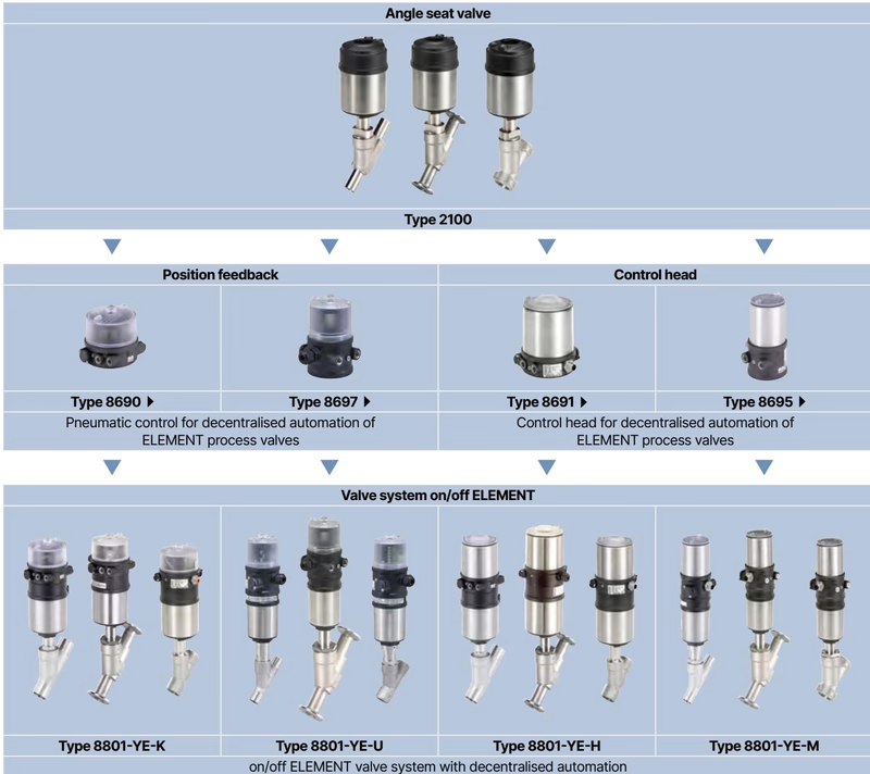
Burkert Type 2100 interfaces directly with the ELEMENT automation architecture to form integrated on/off valve systems (Type 8801-YE):
Explore similar products in our catalog



