


PN25

BURKERT 20141831 (Type 2000) is a pneumatically operated 2/2-way angle seat valve with DN40 G 1 1/2 ports, CF3M stainless steel body, PA actuator, PTFE seal, normally closed function, and 40 m³/h flow capacity.
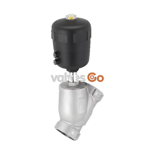
BURKERT 20141831 (Type 2000 CLASSIC) is an externally piloted 2/2-way pneumatically operated angle seat valve designed for shut-off control of liquid and gaseous media. Configured with a precision-cast CF3M (316L) stainless steel body, an 80 mm (Size F) polyamide (PA) piston actuator, and G 1 1/2 internal threaded ports, this valve provides an unrestricted Kv flow coefficient of 40 m³/h. It operates in Control Function A (normally closed by internal spring force) with media flow directed below the valve seat (flow to open), eliminating water hammer in liquid pipe systems.
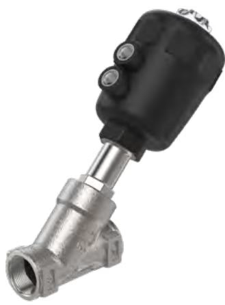
Equipped with a single mechanical stroke limitation mechanism without lock nut, BURKERT 20141831 handles operating pressures from 0.00 bar to 9.00 bar(g) with a minimum required pilot air pressure of 5.0 bar(g) and a maximum of 10.0 bar(g). The valve is rated for media temperatures ranging from -10 °C to +185 °C and ambient operating temperatures from -10 °C to +60 °C. The assembly supports both Clean-in-Place (CIP) and Steam-in-Place (SIP) thermal sanitation protocols, making it suitable for process control involving steam, water, alcohols, oils, fuels, hydraulic fluids, salt solutions, alkaline solutions, and organic solvents.
BURKERT Type 2000 CLASSIC angle seat valves combine a flow-optimized 2-way body with a linear pneumatic piston actuator. Dynamic stem sealing is provided by a self-adjusting packing gland with filled PTFE V-rings preloaded by an internal coil spring, compensating for thermal expansion and mechanical wear across extended switching cycles.
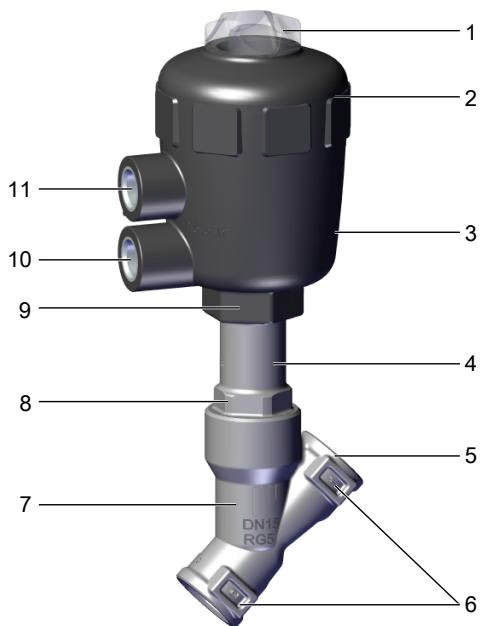
| Item | Component | Material Specification |
|---|---|---|
| 1 | Transparent cover with optical indicator | Polycarbonate (PC) |
| 2 | Pilot air port inserts | Stainless steel 1.4305 (G 1/4) |
| 3 | Actuator housing and bonnet | Polyamide (PA) |
| 4 | Piston seal | Nitrile rubber (NBR) |
| 5 | Stem packing gland | Filled PTFE V-rings with spring compensation |
| 6 | Closing spring | Stainless steel 1.4310 |
| 7 | Internal guide tube | Stainless steel CF3M |
| 8 | Wiper ring | Filled PTFE |
| 9 | Body gasket | Graphite (PTFE optional) |
| 10 | Valve spindle | Stainless steel 1.4401 / 1.4404 |
| 11 | Retaining pin | Stainless steel 1.4401 / 1.4404 |
| 12 | Valve seat seal | Polytetrafluoroethylene (PTFE) |
| 13 | Valve body | Cast stainless steel CF3M (equivalent to 316L) |
| 14 | Swivel plate | Stainless steel CF3M / 1.4404 / 1.4401 |
| — | Actuator relief / overflow bore | Atmospheric vent between body and actuator |
Self-Adjusting Packing Gland
The stem sealing system utilizes chevron PTFE V-rings paired with a 1.4310 stainless steel compression spring. The spring maintains active contact pressure on the packing set without requiring manual gland adjustment throughout service life.
BURKERT 20141831 operates via Control Function A (normally closed, NC). In the unpressurized rest position, the integrated spring pack presses the spindle and swivel plate firmly against the body seat, shutting off media flow. Supplying compressed air to the lower pilot air port overcomes spring force, lifting the swivel plate off the seat to open the valve.
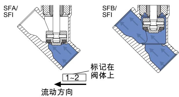
Media flows into the body underneath the valve seat (flow to open). Operating line pressure acts directly against the underside of the swivel plate, assisting the opening motion when pilot pressure is applied. When closing against the incoming stream, the fluid provides continuous dampening, preventing damaging pressure surges (water hammer).
Operating Restriction: Flow Direction Over Seat
Angle seat valves configured for media flow above the seat must never be used with liquid media due to severe water hammer hazards. Flow direction below the seat is certified for both liquid media and compressible media (gases and steam).
BURKERT 20141831 complies with European Pressure Equipment Directive 2014/68/EU and Machinery Directive 2006/42/EC. It achieves Leakage Rate A in accordance with DIN EN 12266-1 when tested with compressed air.
| Specification Parameter | Value / Range |
|---|---|
| Nominal Diameter (DN) | DN 40 (NPS 1 1/2) |
| Seat Diameter | 40 mm |
| Flow Coefficient Kv (Water) | 40 m³/h (Cv = 46.2 GPM) |
| Maximum Operating Pressure | 9.0 bar(g) (0.90 MPa) |
| Nominal Pressure Class | PN 25 (DIN EN 1333) / Class 150 (DIN EN 1759) |
| Minimum Pilot Air Pressure | 5.0 bar(g) |
| Maximum Pilot Air Pressure | 10.0 bar(g) |
| Control Medium | Filtered neutral gases, dry compressed air |
| Maximum Fluid Viscosity | 600 mm²/s |
| Medium Temperature Range | -10 °C to +185 °C |
| Ambient Temperature Range | -10 °C to +60 °C |
| Storage Temperature Limits | -20 °C to +65 °C |
| Enclosure Protection Rating | IP67 (EN 60529 / IEC 60529) |
| Sound Pressure Level | < 70 dB(A) |
| Maximum Installation Altitude | 2,000 m above sea level |
Operating pressure limits must comply with the material pressure-temperature ratings defined by DIN EN 12516-1 (PN25) and ASME B16.34 (Class 150):
| Temperature Range [°C] | DIN EN 12516-1 PN25 Max Pressure [bar] | ASME B16.34 Class 150 Max Pressure [bar] |
|---|---|---|
| -10 °C to +38 °C | 25.0 bar | 19.0 bar |
| +50 °C | 25.0 bar | 18.4 bar |
| +100 °C | 24.5 bar | 16.2 bar |
| +150 °C | 22.4 bar | 14.8 bar |
| +185 °C / +200 °C | 20.3 bar | 13.7 bar |
Pilot Pressure Setting
To guarantee full stroke opening against the maximum 9.0 bar media pressure, supply pilot air at a minimum of 5.0 bar directly to the lower pilot port. Operating below 5.0 bar can cause partial opening or reduced flow capacity.
BURKERT 20141831 features standard G 1 1/2 parallel internal threads compliant with DIN ISO 228-1. The actuator head can be rotated 360° independently of the valve body to position pilot air connections optimally.
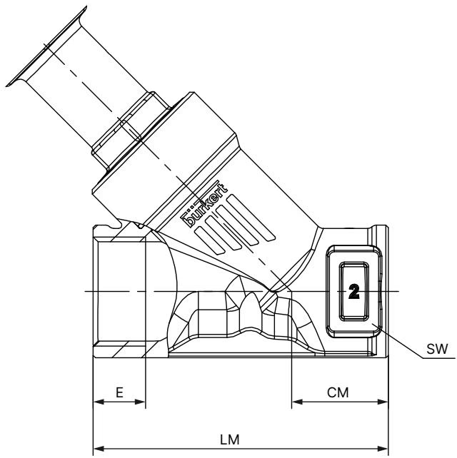
| Dimensional Reference | Measurement [mm / inch] |
|---|---|
| Nominal Diameter (DN / NPS) | DN 40 / NPS 1 1/2 |
| Face-to-Face Body Length (LM) | 120 mm |
| Thread Engagement Depth (E - G thread) | 18 mm |
| Centerline to Body Base (CM) | 35 mm |
| Body Hexagon Wrench Flat (SW) | 55 mm |
| Actuator Outer Diameter (Ø A) | 101 mm (Actuator Size 80 / F) |
| Centerline to Top of Actuator Cap (B / H) | 213 mm |
| Centerline to Pilot Port Center (K / M) | 188 mm |
| Centerline to Top with Indicator Raised (BS / HS) | 277 mm |
| Pilot Air Thread Port (P) | G 1/4 |
The actuator assembly rotates 360° steplessly relative to the piping. Before rotating or servicing the actuator, the valve must be opened pneumatically to prevent mechanical friction damage against the PTFE seat.
| Fastener Interface | Tool Required | Tightening Torque |
|---|---|---|
| Body Interface Hexagon (DN40 / Actuator 80 F) | Open-end wrench AF 55 | 65 Nm (+10 / -5 Nm) |
| Thread Lubrication | Paste compound | Klüberpaste UH1 96-402 |
Preload Protection During Actuator Removal or Rotation
For valves with Control Function A, apply 5.0 bar compressed air to the lower pilot port before unscrewing or rotating the actuator. Attempting to rotate or detach the actuator while the spring presses the swivel plate against the seat will tear the PTFE seal or damage the machined sealing lip.
Pneumatic lines connect to internal G 1/4 threaded ports on the actuator cylinder. Only clean, unlubricated instrument air or neutral gas should be used to prevent chemical degradation of internal NBR piston seals.
The pneumatic actuator is permanently lubricated and maintenance-free. Periodic plant inspection should verify sealing integrity across the exterior joint interfaces.
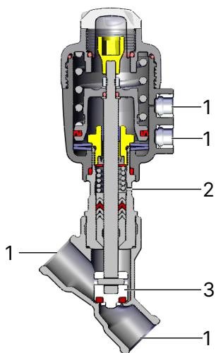
| Inspection Area | Visible Symptom | Corrective Action |
|---|---|---|
| 1: Media Ports | Fluid weeping past pipe threads | Retighten threaded fittings; reapply sealing paste |
| 2: Overflow / Relief Bore | Media seepage through actuator weep hole | Replace stem packing gland kit or replace actuator |
| 3: Swivel Plate / Seat | Internal seat bypass in closed position | Disassemble actuator and install new swivel plate kit |
| —: Body Joint | Fluid leaking at body-to-actuator thread | Replace graphite body gasket; retighten to 65 Nm |
| Malfunction | Root Cause | Remedial Action |
|---|---|---|
| Actuator fails to switch | Control air connected to upper port | Reconnect pilot air line to lower pilot port |
| Pilot pressure below 5.0 bar | Increase supply pressure to nominal 5.0–10.0 bar | |
| Media pressure exceeds 9.0 bar | Verify line pressure does not exceed rated 9.0 bar | |
| Valve installed backwards | Ensure body arrow matches media flow direction | |
| Seat bypass leakage | Foreign particles trapped on seat | Flush line; install upstream strainer (< 1 mm mesh) |
| PTFE seat seal worn or damaged | Replace swivel plate assembly | |
| Pilot pressure not fully exhausted | Check 3/2-way exhaust port for backpressure | |
| Relief bore weeping | Packing V-rings worn by abrasive media | Install process valve packing gland service set |
BURKERT offers matching accessories and installation tooling tailored to Type 2000 angle seat valves with 80 mm (Size F) actuators:
| Accessory Description | Model / Type | Order Code |
|---|---|---|
| Integrated electrical position feedback unit | Type 8697 (mechanical or inductive switches) | Configured by request |
| Direct-mount 3/2-way pilot solenoid valve | Type 6014 (banjo G 1/4, 24 V DC coil) | 334870 |
| Matching cable plug for pilot valve | Type 2518 Form A (12–24 V AC/DC LED) | 314812 |
| Actuator cap disassembly wrench | Ø 80 mm (Size F) cap wrench | 639171 |
| Packing gland socket wrench | AF 21 mm (spindle Ø 14 mm, DN 32–80) | 683223 |
| Packing gland assembly sleeve | Ø 10 mm spindle (Actuator Size 80 / F) | 639168 |
| CF A to CF B conversion kit | Size 80 (F) spring/piston modification kit | 011955 |
| Flow below to above seat conversion kit | Size 80 (F) conversion components | 012005 |
| Control Function | DN | Thread Connection | Actuator Size | Min Pilot Pressure | Max Operating Pressure | Body Material | Actuator Material | Order Code |
|---|---|---|---|---|---|---|---|---|
| A (NC) | 40 | G 1 1/2 | 80 mm (F) | 5.0 bar | 9.0 bar | CF3M (316L) | PA (with stroke limiter) | 20141831 |
| A (NC) | 40 | G 1 1/2 | 80 mm (F) | 5.0 bar | 9.0 bar | CF3M (316L) | PA (standard) | 343142 |
| A (NC) | 40 | G 1 1/2 | 80 mm (F) | 5.0 bar | 9.0 bar | CF3M (316L) | PPS (high temp) | 344673 |
| A (NC) | 40 | G 1 1/2 | 125 mm (H) | 3.2 bar | 16.0 bar | CF3M (316L) | PA | 342695 |
| A (NC) | 40 | G 1 1/2 | 125 mm (H) | 4.1 bar | 25.0 bar | CF3M (316L) | PA | 344989 |
| B (NO) | 40 | G 1 1/2 | 63 mm (E) | Per chart | 25.0 bar | CF3M (316L) | PA | 344696 |
Explore similar products in our catalog



