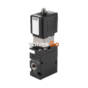
PN16

Burkert 308014 Type 8640 modular valve island for pneumatics. Features 19mm width per station, G 1/4 pressure port, 3/2 valve function, and Fieldbus module.
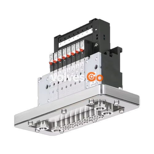
The BURKERT 308014 Type 8640 modular valve island is designed to solve diverse and complex control problems through its systematic modular construction and combination of pneumatic and electrical interfaces. This specific configuration features a 19 mm width per station, a G 1/4 pressure port, a 3/2 valve function, and a Fieldbus module for advanced communication. By putting together a row of pneumatic modules, multiple valve functionalities can be realized on a single unit, making it highly flexible for control cabinet installations.

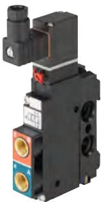
The 19 mm variant utilizes the Type 5470 solenoid valve, which consists of a pneumatic valve body fitted with a Type 6106 rocker pilot valve. An armature with a tilting bearing, similar to a rocker, tilts within the body of the pilot valve to switch the valve. This minimal tilting movement is non-wearing, and basic lubrication is unnecessary.
| Feature | Value |
|---|---|
| Width per station | 19 mm |
| Pressure port | G 1/4 |
| Working port | D6 |
| Nominal pressure | 2 to 10 bar |
| Medium temperature | 0 °C to +50 °C |
| Ambient temperature | 0 °C to +55 °C |
| Valve function | 3/2-way |
| Communication | Fieldbus module |
| Protection class | IP20 (IP65 with suitable connector) |
| Body material | PA (Polyamide) |
| Seal material | NBR |
Operating Conditions
Pilot pressure for the pneumatic control unit depends on the pressure of the flow medium; it must be between 2 and 10 bar (at least 70% of operating pressure). A pressure difference between port 1 and 3 of at least 2 bar is required. When temperatures are below 0 °C, operation is restricted to dried air.
The valves can be mounted on the modular, pneumatic type MP05 base rails to form valve blocks. They can be installed in any position, preferably with the solenoid actuator on top.
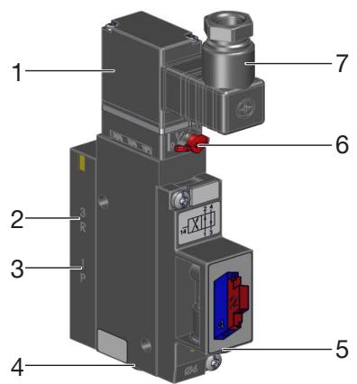
| Item | Designation |
|---|---|
| 1 | Pilot valve Type 6106 |
| 2 | Exhaust port 3 |
| 3 | Pressure port 1 |
| 4 | Working port 4 |
| 5 | Working port 2 |
| 6 | Manual override |
| 7 | Cable plug Type 2506 |
To operate the valve manually, press the manual override and turn it 90° clockwise (until it stops). The manual override is locked and does not reset automatically.
WARNING
Only operate the manual override when the power is off.
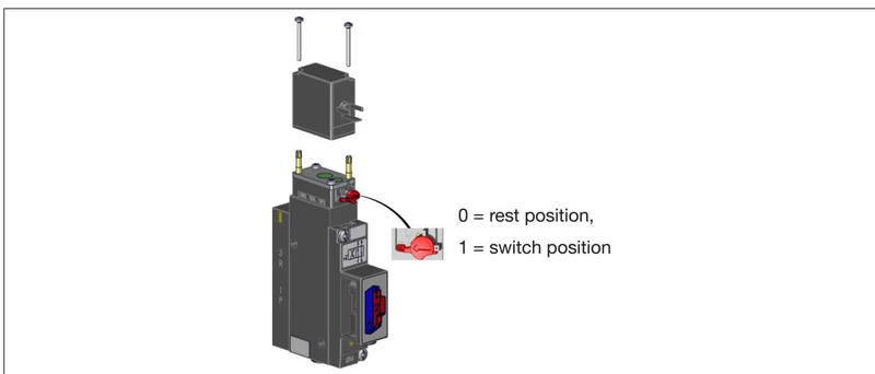
This configuration operates primarily with a 3/2-way valve function. However, the Type 5470 valve design allows for conversion between 4/2 and 3/2-way functions depending on the application requirements.
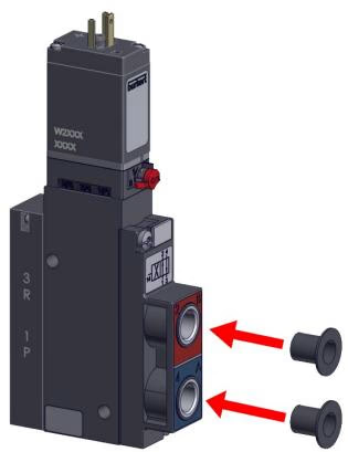
To convert a 4/2-way valve to a 3/2-way valve, close port 2 or port 4 with a stopper depending on the desired circuit function:
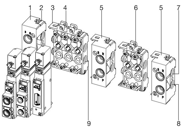
Begin installation with the connection module on the left. Check modules for complete installation with 2 O-rings each. Lightly oil or grease all O-rings before engaging.
TIP
Insert 3 O-rings into the recess on the back of the valve and ensure that the seal is properly fitted. Crushed O-rings and profile seals lead to leaky blocks.
The valve block can be mounted on a standard rail (35 x 15 or 35 x 7.5 EN 50022) or directly to a wall.
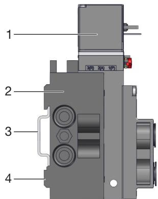
Standard rail installation:
Push the hose lines into the push-in connections of the solenoid valves until they come to a stop. Use PTFE tape or elastomer seal for sealing the threaded connection.
Tightening Torques:
DANGER
Risk of injury due to electric shock. Switch off voltage before working on the device or system. Secure against reactivation. When installing, make sure that the coil is firmly seated on the valve body so the protective conductor connection of the coil is connected to the valve body.
Screw on the cable plug observing the maximum tightening torque of 0.3 Nm. Check that the seal is correctly fitted. Connect the protective conductor and check electrical continuity between the coil and housing (Maximum 0.1 Ω at 12 V / 1 A).
| Fault | Possible cause | Remedy |
|---|---|---|
| Valves do not switch | No operating voltage or operating voltage too low | Check electrical connection. Ensure operating voltage according to type label. |
| Manual override not in zero position | Bring manual override to zero position. | |
| Pressure supply insufficient or not available | Set up large-volume pressure supply. Minimum operating pressure ≥ 2 bar. | |
| Valves switch with a delay or blow off at exhaust | Pressure supply insufficient or not available | Set up large-volume pressure supply. Minimum operating pressure ≥ 2 bar. |
| Valves are not in the home position during pressure build-up | Apply pressure to the valve block before the valves are switched. | |
| Impurities or foreign matter in the pilot or pneumatic valve | Apply pulsed pressure to the exhaust air ducts to blow out impurities. Install a new valve. | |
| Leaky valve blocks | Missing or crushed O-rings between modules | Identify leak or missing seals. |
| Missing or incorrectly positioned flat seals | Insert missing seals or replace damaged seals. |
Explore similar products in our catalog