


PN25

BURKERT 344543 is a Type 2000 DN25 pneumatic 2/2-way angle seat valve with welded connection, PA actuator, normally closed CFA, PTFE seal, 0-25 bar rating, and 19 m3/h Kv.
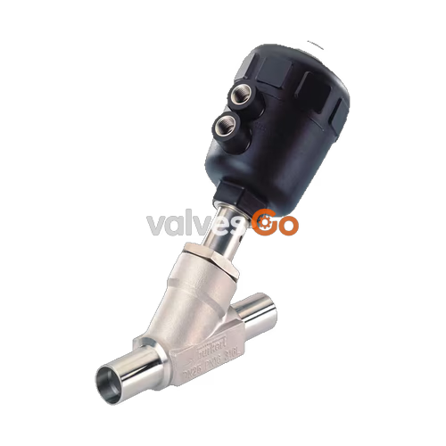
BURKERT 344543 is a Type 2000 CLASSIC 2/2-way pneumatically operated angle seat valve designed for on/off fluid isolation in industrial processes. Featuring a cast stainless steel CF3M (316L) body and welded pipe ends conforming to ISO 4200, DIN EN ISO 1127, and DIN 11866 Series B (DN 25, outer diameter 33.7 mm, wall thickness 2.0 mm), the valve pairs a polyamide (PA) piston actuator with a self-adjusting PTFE V-ring packing gland.
Configured in Control Function A (normally closed by spring force) with fluid flow introduced below the valve seat, article 344543 delivers a flow coefficient Kv of 19 m³/h and maintains bubble-tight shut-off across operating pressures from 0 to 25 bar(g). The flow-below-seat design prevents liquid water hammer when cycling liquid and steam media. The unit requires 5.0 to 10.0 bar(g) pilot pressure, carries an IP67 enclosure rating, and supports Clean-in-Place (CIP) and Sterilization-in-Place (SIP) operations across medium temperatures from -10 °C to +185 °C.
BURKERT 344543 consists of an angle seat valve body and a pneumatic piston actuator. The actuator housing is manufactured from glass-fiber-reinforced polyamide (PA), with a transparent polycarbonate cover that integrates a visual position indicator. The linear thrust generated by internal springs or pilot air transmits through a stainless steel spindle (1.4401/1.4404) to a swivel plate fitted with a PTFE seat seal disc.
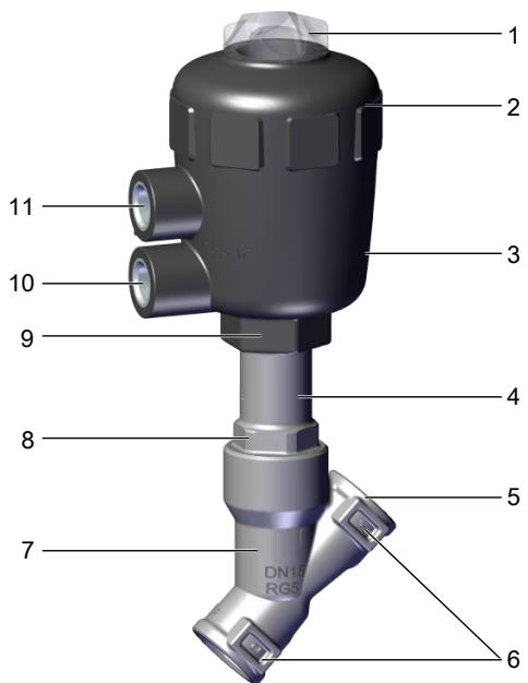
| Item | Component Description | Item | Component Description |
|---|---|---|---|
| 1 | Transparent cover with position indicator | 7 | Valve body (CF3M stainless steel) |
| 2 | Actuator cover | 8 | Body connection with wrench flats |
| 3 | Actuator housing (PA) | 9 | Spindle assembly |
| 4 | Relief / overflow bore | 10 | Lower pilot air port (G 1/4) |
| 5 | Welded pipe port (DN 25) | 11 | Upper pilot air port (G 1/4, plugged for CFA) |
| 6 | Flow direction marking |
Under Control Function A (SFA / CFA), internal preloaded springs press the spindle downward, keeping the PTFE seal seated against the orifice in the unpressurized rest position. When pilot air enters the lower control port (Port 10), the pneumatic piston compresses the spring stack and lifts the seal disc away from the seat.
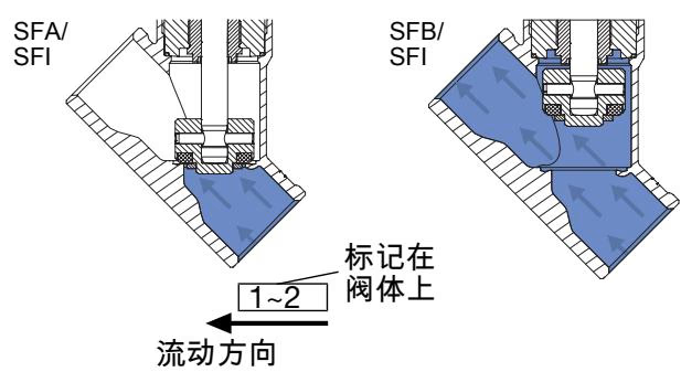
Fluid flows under the seat (closing against the medium flow). Upstream process pressure acts against the underside of the swivel plate, which assists valve opening and eliminates the pressure surges associated with flow-over-seat shut-off in liquid systems.
| Parameter | Technical Specification |
|---|---|
| Valve Type | 2000 CLASSIC |
| Article Number (MPN) | 344543 |
| Port Size (DN / NPS) | DN 25 / NPS 1 |
| Connection Standard | ISO 4200 / DIN EN ISO 1127 / DIN 11866 Series B |
| Pipe Outer Diameter (OD) x Wall Thickness (WT) | 33.7 mm x 2.0 mm (Inner Diameter: 29.7 mm) |
| Control Function | A (normally closed, NC) |
| Flow Direction | Below valve seat (flow to open) |
| Flow Factor Kv (Water at +20 °C, Δp = 1 bar) | 19 m³/h |
| Seat Orifice Diameter | 25 mm |
| Seat Leakage Rate | Leakage Rate A (DIN EN 12266-1, test medium air) |
| Working Medium Pressure | 0 to 25 bar(g) |
| Nominal Pressure Class | PN 25 (DIN EN 1333) / Class 150 (DIN EN 1759) |
| Pilot Air Pressure | 5.0 to 10.0 bar(g) |
| Pilot Air Connection | G 1/4 internal thread |
| Medium Temperature | -10 °C to +185 °C |
| Ambient Temperature | -10 °C to +60 °C |
| Storage Temperature | -20 °C to +65 °C |
| Permissible Fluid Viscosity | Max. 600 mm²/s |
| Enclosure Rating | IP67 (EN 60529 / IEC 60529) |
| Operating Media | Steam, water, neutral gases, alcohols, oils, fuels, hydraulic fluids, saline solutions, lyes, organic solvents |
| Control Medium | Neutral gases, instrument air |
The maximum permissible working pressure decreases with rising medium temperature in accordance with international pressure vessel and valve body design standards.
| Temperature [°C] | DIN EN 12516-1 PN25 Max Pressure [bar(g)] | ASME B16.34 Class 150 Max Pressure [bar(g)] |
|---|---|---|
| -10 to +38 / +50 | 25.0 | 19.0 |
| 100 | 24.5 | 16.2 |
| 150 | 22.4 | 14.8 |
| 185 (Max for PA/PTFE) | 21.0 | 14.0 |
| 200 | 20.3 | 13.7 |
| 230 | 19.0 | 12.7 |
Ambient Temperature Limits
For Type 2000 valves equipped with polyamide (PA) actuators, continuous operation at the maximum medium temperature of +185 °C requires maintaining the ambient temperature within the rated limit of -10 °C to +60 °C.
| Part Number | Component | Standard Material Specification |
|---|---|---|
| 1 | Transparent Cover | Polycarbonate (PC) |
| 2 | Pilot Air Ports | Stainless steel 1.4305 |
| 3 | Actuator Housing | Polyamide (PA) |
| 4 | Piston Seal | NBR |
| 5 | Packing Gland Seal | PTFE V-rings (filled), spring compensated |
| 6 | Actuator Springs | Stainless steel 1.4310 |
| 7 | Internal Tube | Stainless steel CF3M |
| 8 | Wiper Ring | PTFE (filled) / PEEK |
| 9 | Body Seal | Graphite (PTFE optional) |
| 10 | Valve Spindle | Stainless steel 1.4401 / 1.4404 |
| 11 | Retaining Pin | Stainless steel 1.4401 / 1.4404 |
| 12 | Seat Seal Disc | PTFE |
| 13 | Valve Body | Cast stainless steel CF3M (316L) |
| 14 | Swivel Plate (Disc Holder) | Stainless steel CF3M / 1.4404 / 1.4401 |
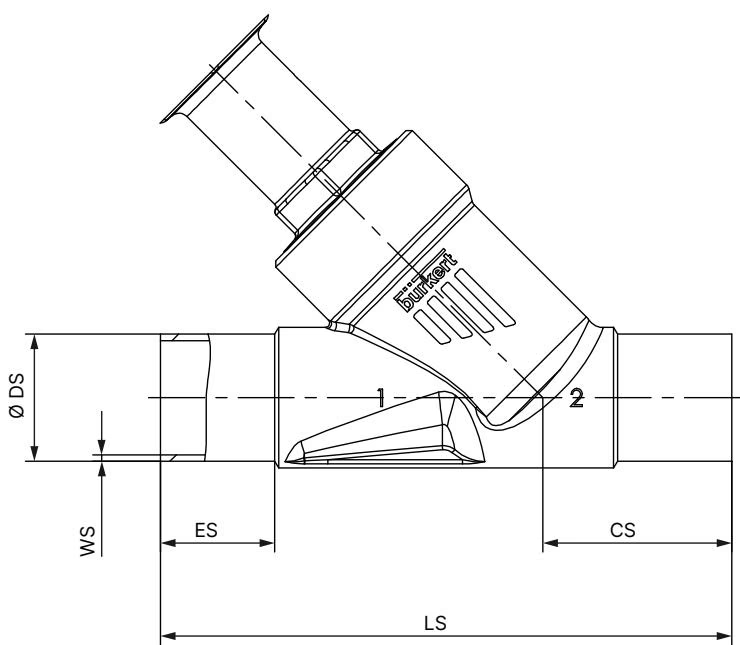
| DN (Port Size) | ES [mm] | CS [mm] | LS [mm] | Ø DS [mm] | WS [mm] | Inner Diameter [mm] |
|---|---|---|---|---|---|---|
| DN 15 | 19 | 34 | 100 | 21.3 | 1.6 | 18.1 |
| DN 20 | 20 | 39 | 115 | 26.9 | 1.6 | 23.7 |
| DN 25 (344543) | 26 | 43 | 130 | 33.7 | 2.0 | 29.7 |
| DN 32 | 26 | 45 | 145 | 42.4 | 2.0 | 38.4 |
| DN 40 | 26 | 49 | 160 | 48.3 | 2.0 | 44.3 |
| DN 50 | 26 | 50 | 175 | 60.3 | 2.0 | 56.3 |
| Actuator Size | Ø A [mm] | B / H [mm] | K / M [mm] | P (Pilot Port) | BS / HS Overall Height [mm] |
|---|---|---|---|---|---|
| 63 (E) | 80 | 178 | 159 | G 1/4 | 242 |
| 80 (F) (344543) | 101 | 195 | 171 | G 1/4 | 259 |
Actuator Dimension Tolerance
Dimensions B, H, K, M, HS, and BS represent maximum outer dimensions and can decrease by up to 6 mm depending on manufacturing tolerance and specific pipe standard.
Mandatory Actuator Removal for Welded Housings
Prior to welding the valve body into the pipeline, the pneumatic actuator must be completely removed from the body. Welding heat conducted through the stainless steel casting will destroy the PTFE seat seal, spindle packing gland, and actuator piston seals.
To align the pilot air port with site pneumatic tubing, rotate the actuator relative to the body.
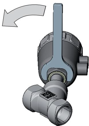
Rotation Direction Restriction
Apply 5.0 bar compressed air to the lower pilot port before turning the actuator. Hold the body connection hexagon with an open-end wrench and turn only the actuator hex part in the direction indicated on the illustration. Rotating in the opposite direction can unscrew the body joint and cause external fluid leakage.
Water Hammer Hazard with Liquid Media
Article 344543 is configured exclusively for flow below the valve seat. Never reverse installation flow direction over the seat when handling liquid media; rapid closing with fluid above the seat creates severe hydraulic shock waves (water hammer) that can rupture piping and valve bodies.
Type 2000 actuators are maintenance-free under normal operating conditions. Regular preventive maintenance focuses on visual leak inspection across four critical points.
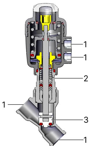
| Inspection Point | Observed Fault | Remedial Action |
|---|---|---|
| 1. Pipe Connection | External fluid leak at welded seam | Reseal or reweld pipe connection |
| 2. Overflow / Relief Bore | Medium dripping from actuator base bore | Spindle packing gland worn; replace packing gland set |
| 3. Valve Seat | Continuous flow when valve is de-energized | Seat seal worn or particulates trapped; flush line or replace valve set |
| 4. Body Joint | External leakage between body and actuator | Replace graphite body seal and torque connection to 60 Nm |
| Symptom | Probable Cause | Corrective Action |
|---|---|---|
| Actuator fails to switch | Pilot air pressure below 5.0 bar | Increase pilot pressure to 5.0–10.0 bar range |
| Pilot air line connected to upper port | Reconnect pilot line to lower port (Port 10) | |
| Working medium pressure exceeds 25 bar | Verify line pressure against rating plate limits | |
| Internal seat leakage | Debris or swarf trapped under seat | Disassemble and install upstream strainer (mesh < 1 mm) |
| PTFE seat seal eroded or mechanically scored | Install new swivel plate / seal disc set | |
| Fluid leaks at relief bore | Spindle V-ring pack worn | Replace packing gland seal assembly using dedicated tools |
Explore similar products in our catalog



