


PN25

BURKERT 344605 (Type 2000) is a pneumatically operated 2/2-way angle seat valve with stainless steel body, DN 8 ISO 4200 weld ends, 50 mm PA actuator, NC function A, and 0–16 bar operating pressure.
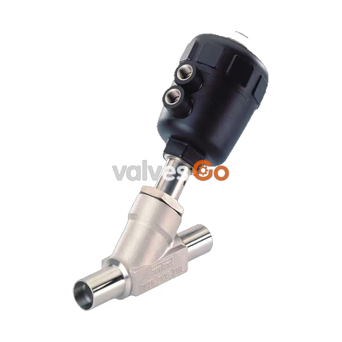
BURKERT 344605 (Type 2000) is an externally piloted 2/2-way pneumatic angle seat valve configured with a cast stainless steel body (CF3M / 316L) and a polyamide (PA) piston actuator of size 50 (D). The valve operates under control function A (normally closed, NC by spring force) with process fluid directed below the valve seat (flow to open). Process pipe integration is implemented via welded ends according to ISO 4200, DIN EN ISO 1127, and DIN 11866 Series B, with an outer pipe diameter of 13.5 mm and a wall thickness of 1.6 mm (port size DN 8, seat orifice DN 15). Rated for liquid and gaseous media, BURKERT 344605 provides a nominal flow factor Kv of 2.5 m³/h, a working pressure span from 0 to 16 bar(g), and a process temperature capability of -10 °C to +185 °C.
The drive assembly transmits spring closure force through a precision ground 1.4401 / 1.4404 stainless steel spindle directly to the CF3M swivel plate. Positive shut-off against the PTFE seat seal achieves Leakage Rate A in accordance with DIN EN 12266-1 with air test media. Spindle sealing is maintained by a self-adjusting packing gland comprising spring-compensated, filled PTFE V-rings and a PTFE wiper. Compressed pilot air enters through an internal G 1/4 thread connection, requiring a minimum pilot pressure of 4.1 bar(g) up to a maximum of 10 bar(g). The PA actuator features an optical position indicator housed under a clear polycarbonate bonnet, an IP67 enclosure rating, and continuous 360° rotational positioning for pilot air line alignment.
BURKERT 344605 features high chemical resistance and mechanical strength throughout its fluidic and pneumatic sections. The flow-optimised angle seat body geometry ensures laminar transition and reduced pressure drop.
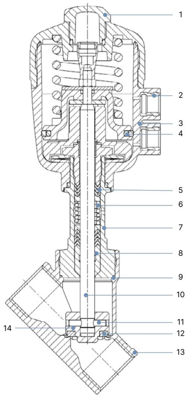
| Item | Component | Material |
|---|---|---|
| 1 | Transparent bonnet / position indicator | Polycarbonate (PC) |
| 2 | Pilot air connection inserts | Stainless steel 1.4305 |
| 3 | Actuator body | Polyamide (PA) |
| 4 | Piston seal | Nitrile butadiene rubber (NBR) |
| 5 | Spindle packing gland | Filled PTFE V-rings with stainless steel spring compensation |
| 6 | Actuator spring set | Stainless steel 1.4310 |
| 7 | Guiding tube | Stainless steel CF3M |
| 8 | Wiper | Filled PTFE |
| 9 | Body gasket | Graphite (PTFE optional) |
| 10 | Valve spindle | Stainless steel 1.4401 / 1.4404 |
| 11 | Retention pin | Stainless steel 1.4401 / 1.4404 |
| 12 | Seat seal | Polytetrafluoroethylene (PTFE) |
| 13 | Valve body | Stainless steel CF3M (equivalent to 316L) |
| 14 | Swivel plate | Stainless steel CF3M / 1.4401 / 1.4404 |
BURKERT 344605 uses control function A (CF A). In the unpressurized rest state, internal helical springs force the actuator piston downward, seating the PTFE seal plate tightly against the orifice to close the valve.
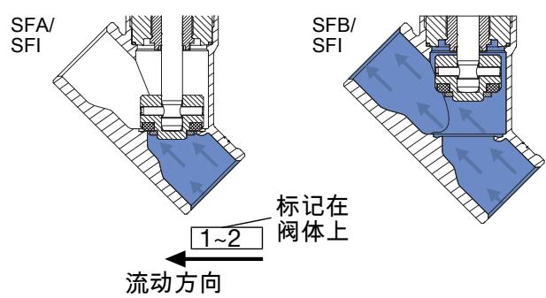
Process media enters through port 1 beneath the valve seat and discharges through port 2. The medium pressure acts against the underside of the swivel plate, assisting the opening motion when compressed control air is applied to the lower pilot port (port 10). Because closing occurs against the direction of fluid travel, sudden line shocks and hydraulic water hammer are effectively eliminated in liquid circuits.
Operating Restriction: Flow Direction
Valves configured with flow direction above the seat must not be used for liquid media due to the severe hazard of pipe burst caused by water hammer. BURKERT 344605 is built specifically for flow below the seat, making it fully approved for liquid media as well as gases and steam.
BURKERT 344605 conforms to European Pressure Equipment Directive 2014/68/EU and Machinery Directive 2006/42/EC. It is suitable for water, alcohols, oils, fuels, hydraulic fluids, saline solutions, lyes, organic solvents, neutral gases, and clean saturated steam.
| Specification Parameter | Value |
|---|---|
| Port connection size | DN 8 (pipe outer diameter 13.5 mm) |
| Pipe connection standard | ISO 4200 / DIN EN ISO 1127 / DIN 11866 Series B |
| Pipe dimensions (OD x WS) | 13.5 mm x 1.6 mm (inner diameter 10.3 mm) |
| Orifice seat diameter | DN 15 (15 mm) |
| Flow factor Kv (water, +20 °C, 1 bar Δp) | 2.5 m³/h |
| Flow factor Cv (US gpm) | 2.89 gpm |
| Nominal pressure rating | PN 25 (DIN EN 1333) / Class 150 (DIN EN 1759) |
| Operating medium pressure range | 0 to 16 bar(g) |
| Required minimum pilot pressure | 4.1 bar(g) |
| Maximum pilot pressure | 10 bar(g) |
| Pilot control fluid | Filtered air, neutral gases |
| Process medium temperature range | -10 °C to +185 °C |
| Permissible ambient temperature | -10 °C to +40 °C (maximum envelope up to +60 °C) |
| Valve body pressure rating limit | PN 25 (25 bar at -10 to +50 °C; 22.4 bar at 150 °C; 20.3 bar at 200 °C) |
| Viscosity limit | Maximum 600 mm²/s |
| Sound pressure level | < 70 dB(A) |
| Cleaning compatibility | CIP (Clean-in-Place) and SIP (Sterilisation-in-Place) capable |
Dimensional verification is required during piping pre-fabrication and clearance planning. The ISO 4200 welded connection is machined directly into the cast CF3M stainless steel body.
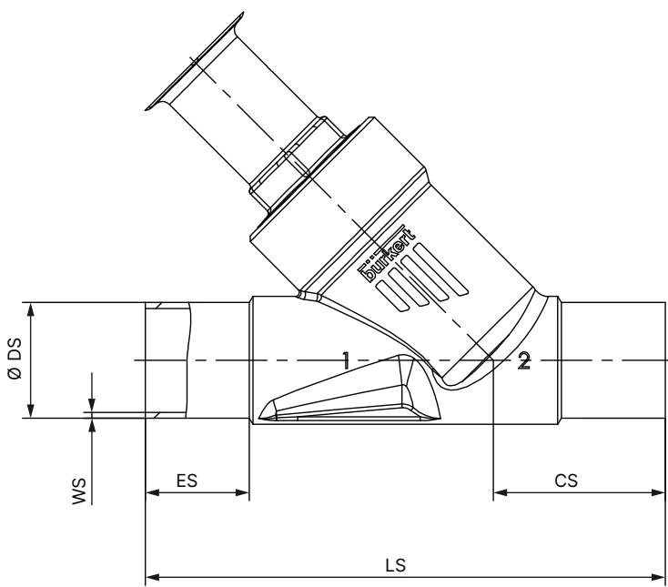
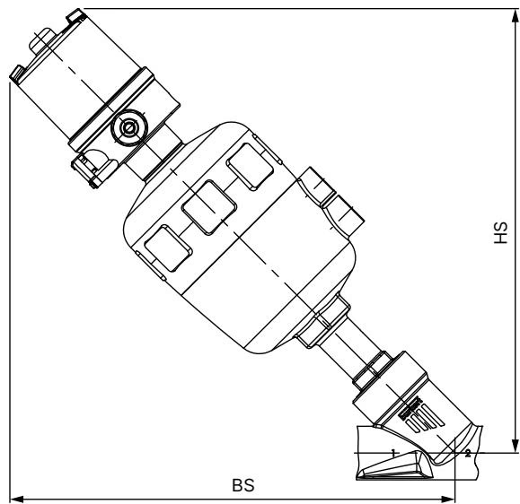
| Dimension Code | Component / Section | Dimension Value |
|---|---|---|
| LS | Total valve body length (face-to-face weld ends) | 100 mm |
| ES | Welded spigot cylindrical end length | 20 mm |
| CS | Centerline to bottom body clearance | 34 mm |
| ∅ DS | Pipe outer diameter | 13.5 mm |
| WS | Pipe wall thickness | 1.6 mm |
| ∅ A | Actuator casing outer diameter | 64 mm (Size 50 / D) |
| B / H | Centerline to top of transparent bonnet | 145 mm (maximum) |
| K / M | Centerline to pilot air connection axis | 129 mm (maximum) |
| P | Pilot air thread connection | G 1/4 |
| BS / HS | Overall clearance envelope along diagonal spindle axis | 216 mm (maximum) |
BURKERT 344605 may be mounted in any orientation, although mounting with the actuator pointing upright is recommended to minimize particulate settling in the stem guide.
Installation Mandatory Procedure: Orbital / Manual Welding
Prior to welding the stainless steel valve body into the pipeline, the pneumatic actuator must be completely removed from the body. Welding heat conducted through the metal will destroy internal PTFE packing seals, NBR piston seals, and graphite gaskets if the actuator remains attached.
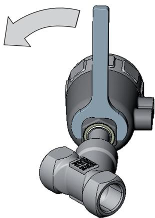
The pneumatic pilot ports can be aligned continuously across 360° to facilitate clean hose dressing:
The PA piston actuator operates maintenance-free under normal operating conditions. Regular maintenance schedules should focus on external leak detection and dynamic sealing elements.
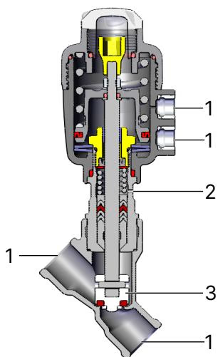
| Inspection Point | Observed Fault | Corrective Action |
|---|---|---|
| Media Connection (1) | Leakage at pipeline weld | Re-weld or re-align connecting piping |
| Relief / Overflow Bore (2) | Media weeping through spindle guide hole | PTFE packing gland worn; replace packing set or actuator |
| Valve Seat / Swivel Plate (3) | Internal seat passage bypass | Foreign particulate or worn PTFE seal; replace valve seat disc set |
| Body Joint Gasket | Fluid escaping between body and actuator | Replace graphite body gasket and retorque to 45 Nm |
| Operational Malfunction | Potential Cause | Solution |
|---|---|---|
| Actuator fails to open | Pilot air connected to wrong port | Connect pilot supply to lower port (port 10) for CF A |
| Insufficient pilot pressure | Raise pilot air supply to at least 4.1 bar(g) (max 10 bar(g)) | |
| Excessive working line pressure | Verify process line pressure does not exceed 16 bar(g) | |
| Reverse process flow direction | Verify flow enters below the seat according to arrow markings | |
| Seat passes fluid when closed | Debris trapped in valve seat orifice | Flush piping; install an upstream strainer with mesh ≤ 1 mm |
| PTFE seat seal worn or gouged | Install replacement swivel plate kit (spare parts kit) | |
| Continuous leakage from relief bore | Packing gland V-rings worn | Replace spindle packing gland seal set using special assembly sleeve |
Original Spare Parts and Accessories
Genuine replacement valve seat sets (comprising seal holder, PTFE seat seal, centering nut, and replacement graphite gasket) and complete packing gland maintenance kits are available through Bürkert distribution networks. To ensure operational safety and pressure compliance, use only original manufacturer components.
Explore similar products in our catalog



