

PN16

BURKERT 349264 (Type 8640) is a 24-bank modular pneumatic valve island with 19 mm station width, G 1/4 supply ports, D6 bottom working connections, 2-10 bar operating pressure, and collective socket interface.
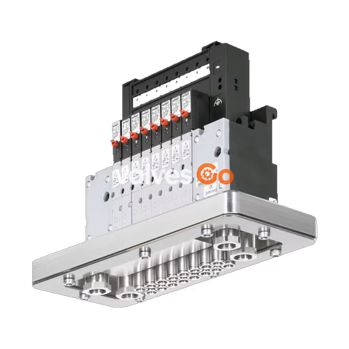
BURKERT 349264 (Type 8640) is a 24-bank modular pneumatic valve island configured with a 19 mm station width and equipped with Type 5470 pilot solenoid valves. The unit integrates pneumatic connection modules and electrical collective wiring into a compact block for direct mounting on EN 50022 standard rails. Operating across a pressure range of 2.0 to 10.0 bar and an operating temperature range of 0 °C to 50 °C, the island features G 1/4 pneumatic supply and exhaust channels alongside D6 push-in working connections positioned at the valve bottom.
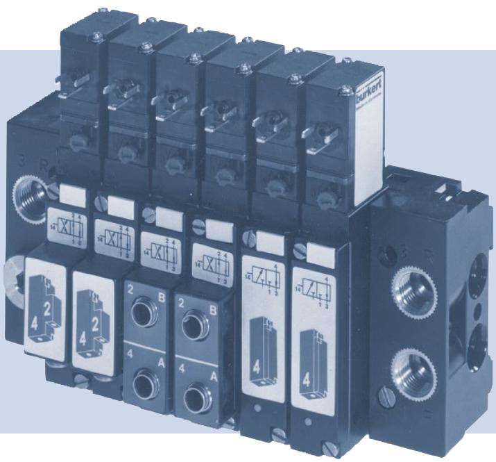
Type 8640 valve islands utilize a systematic modular architecture comprising pneumatic multi-blocks, base rails, and dedicated electrical interface modules. Snap connectors hold the polyamide bodies together securely without external tie rods. Each station on this configuration incorporates a Type 5470 pneumatic valve driven by a Type 6106 rocker pilot valve.
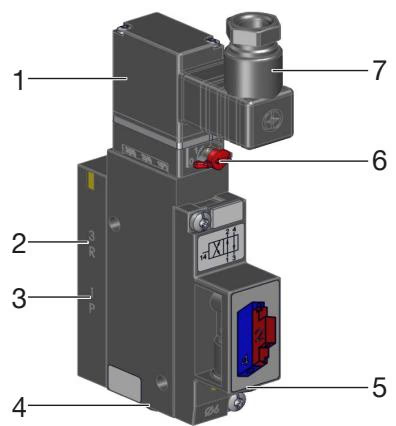
The Type 6106 rocker pilot utilizes an armature with a tilting bearing that pivots within the pilot body to switch pneumatic flow. Because the minimal tilting movement involves no sliding friction, the pilot is non-wearing and requires no initial lubrication.
| Item | Designation |
|---|---|
| 1 | Pilot valve Type 6106 |
| 2 | Exhaust port 3 (R) |
| 3 | Pressure port 1 (P) |
| 4 | Working port 4 (A) |
| 5 | Working port 2 (B) |
| 6 | Manual override |
| 7 | Cable plug interface (Type 2506 / Type 2516) |
All pneumatic connections on the valve island are labeled numerically according to standard fluid power conventions:
Each Type 5470 valve station includes a mechanical manual override on the actuator body for system commissioning and manual operation during testing.
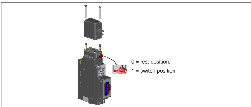
Manual Override Procedure
To actuate the valve manually, press the manual override pin and rotate it 90° clockwise until it hits the mechanical stop. In this position, the override remains locked and does not automatically reset. Rotate back 90° counterclockwise to disengage before restoring electrical operation. Operate the manual override only when electrical control signals are switched off.
Type 5470 valves support multiple circuit functions. The primary 4/2-way configuration can be converted into 3/2-way functionality on-site by closing one of the working ports with a dedicated plug.
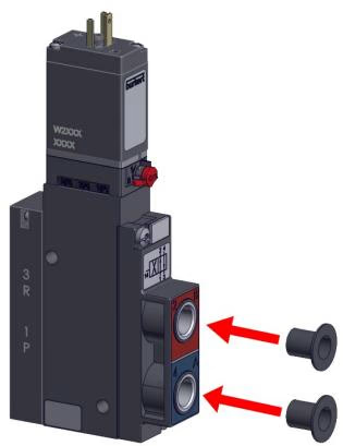
| Desired Circuit Function | Port 2 (B) | Port 4 (A) | Functional Description |
|---|---|---|---|
| Circuit function C (3/2-way NC) | Closed (plugged) | Open | In rest position, pressure port 1 is closed; working port 4 is exhausted to port 3. |
| Circuit function D (3/2-way NO) | Open | Closed (plugged) | In rest position, pressure port 1 is connected to working port 2; exhaust port 3 is closed. |
| Circuit function G (4/2-way) | Open | Open | In rest position, pressure port 1 feeds working port 2; working port 4 exhausts through port 3. |
| Specification Parameter | Technical Value |
|---|---|
| Valve Island Type | 8640 |
| Station Width | 19 mm (Type 5470) |
| Slot Capacity | 24 valve positions |
| Operating Pressure Range | 2.0 to 10.0 bar |
| Minimum Pilot Pressure Differential | ≥ 2 bar difference between port 1 and port 3 |
| Pilot Pressure Requirement | Must be at least 70% of operating pressure |
| Air Flow Rate QNn | 300 l/min (measured at +20 °C, 6 bar inlet, 1 bar Δp) |
| Fluid Media | Filtered compressed air (particle size ≤ 10 μm, unlubricated or lubricated), neutral gases (5 μm) |
| Operating Temperature | 0 °C to +50 °C (ambient and medium) |
| Body / Seal Material | Polyamide (PA) / Nitrile butadiene rubber (NBR) |
| Supply Connections 1 (P), 3 (R) | G 1/4 female thread |
| Working Connections 2 (B), 4 (A) | Push-in fittings D6 mm located at valve bottom |
| Nominal Operating Voltage | 24 V DC (±10% tolerance, ripple ≤ 1 Vss) |
| Nominal Power per Valve | 1 W to 2 W (standard 2 W coil) |
| Electrical Duty Cycle | 100% continuous operation (ED) |
| Electrical Protection Class | Class III according to VDE 0580 |
| Ingress Protection | IP20 (terminal module); IP65 achievable with sealed Type 2516 cable plug |
Continuous Operation Reliability
When operating valves under continuous energization or during extended downtimes, perform at least 1 to 2 switching cycles per day to ensure complete functional reliability and prevent seal sticking.
The 19 mm pneumatic base system is assembled from modular multi-blocks linked by latching tabs, sealed by internal O-rings, and secured to mounting surfaces.
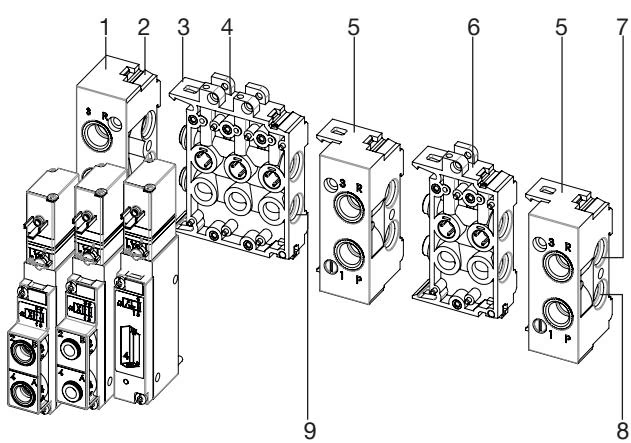
| Item | Component | Item | Component |
|---|---|---|---|
| 1 | Left connection module | 6 | Base module (2-fold) |
| 2 | Latch tab | 7 | Exhaust channel 3 (R) |
| 3 | Latch hook | 8 | Supply channel 1 (P) |
| 4 | Base module (3-fold) | 9 | Sealing O-ring |
| 5 | Right connection module | - | - |
Prevent Pneumatic Leaks
Crushed, pinched, or missing O-rings and profile seals between modular blocks cause line leakage. Ensure all seals are seated cleanly in their grooves prior to latching adjacent sections together.
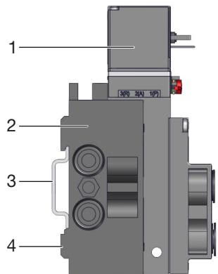
To mount the valve island on an EN 50022 standard DIN rail (35 x 7.5 mm or 35 x 15 mm):
When installing threaded fittings into the connection modules, observe the following torque limits:
| Port Size | Port Function | Recommended Torque | Maximum Torque |
|---|---|---|---|
| G 1/4, NPT 1/4 | Supply port 1 (P), exhaust port 3 (R) | 4 to 7 Nm | 20 Nm |
| G 1/8, NPT 1/8 | Working ports 2 (B), 4 (A) | 3 to 6 Nm | 7 Nm |
Pressure and Fluid Discharge Hazard
High pressure and uncontrolled venting can cause severe physical injury. Depressurize and drain all pneumatic feed lines completely before tightening fittings, disassembling blocks, or performing maintenance.
Pneumatic push-in connectors conform to ISO 14743:2020. Observe tube specifications to maintain leak-tight joints and retention forces.
| Tubing Material | Tubing Outer Diameter (OD) | Permitted Deviation |
|---|---|---|
| Polyamide (PA) | 3 to 10 mm | ±0.08 mm |
| Polyamide (PA) | 12 to 16 mm | ±0.10 mm |
| Polyurethane (PU) | 3 to 8 mm | ±0.10 mm |
| Polyurethane (PU) | 10 to 16 mm | ±0.15 mm |
| Tube OD Metric | 3 mm | 4 mm | 6 mm | 8 mm | 10 mm | 12 mm | 14 mm | 16 mm |
|---|---|---|---|---|---|---|---|---|
| Tube OD Imperial | 1/8" | 5/32" | 1/4" | 5/16" | 3/8" | 1/2" | - | 5/8" |
| Min. Tensile Force PA (N) | 60 | 70 | 120 | 170 | 250 | 300 | 300 | 350 |
| Min. Tensile Force PU (N) | 25 | 50 | 100 | 150 | 200 | 200 | 250 | 300 |
When softer or flexible polyurethane (PU) tubing is utilized, install internal support sleeves (Article 20099400) to ensure mechanical stability and seal tightness under pressure.
Article 349264 uses a collective socket module (parallel wiring) with screw-type terminals for up to 24 valves, providing a looped-through ground potential and IP20 protection. Total current drawn across the collective connection must not exceed 3 A.
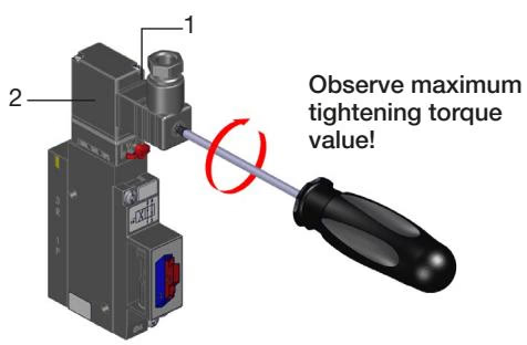
When individual Type 5470 coils are accessed via Type 2516 cable plugs (DIN EN 175301-803 Form C):
Risk of Electric Shock
Failure of the protective earth conductor connection poses an electric shock hazard. Always verify continuity between the coil ground pin and the valve body before energizing the island.
| Plug Configuration | Pilot Valve State | Pneumatic Port Path (WWG) | Pneumatic Port Path (WWC) |
|---|---|---|---|
| (+) on pin 2 / (-) on pin 1 | Pilot valve opens | 1 to 3 / 2 to 3 | 1 to 4 |
| (+) on pin 1 / (-) on pin 2 | Pilot valve closes | 1 to 2 / 4 to 3 | 4 to 3 |
Polarity and Pulse Requirement
Correct polarity is mandatory for impulse-type coils. Maintain a minimum control pulse duration of 50 ms to ensure positive valve spool transition.
| Malfunction | Possible Cause | Corrective Action |
|---|---|---|
| Valves fail to switch | No supply voltage or operating voltage below 24 V DC ±10% | Verify power supply and wiring on collective terminal block. Ensure nominal voltage reaches coil. |
| Manual override locked in actuated position | Disengage manual override and return to 0 (neutral) position. | |
| Feed pressure insufficient (< 2 bar) | Verify compressed air supply; set main regulator to deliver at least 2.0 bar across all active stations. | |
| Delayed switching or continuous exhaust blow-off | Feed pressure insufficient or pressure drop during multi-valve cycling | Increase upstream line volume and verify upstream air maintenance units can meet peak demand. |
| Valves energized prior to pneumatic pressurization | Apply system air pressure to port 1 before transmitting electrical switching signals. | |
| Excessive back pressure in exhaust lines due to clogged silencers | Clean or replace exhaust silencers on port 3; size exhaust ducts to prevent restriction. | |
| Particulate contamination inside valve mechanism | Flush pilot and main spool passages with pulsed air; replace contaminated pilot or valve elements. | |
| External leakage at module joints | O-rings missing, displaced, or pinched between modules | Disassemble sub-blocks and install fresh O-rings; verify flat seals between valves and base modules. |
Explore similar products in our catalog


